HARDWARE
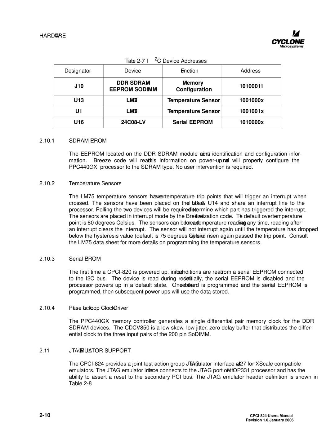
Table 2-7. I2C Device Addresses
Designator | Device | Function | Address | |
|
|
|
| |
J10 | DDR SDRAM | Memory | 10100011 | |
EEPROM SODIMM | Configuration | |||
|
| |||
|
|
|
| |
U13 | LM75 | Temperature Sensor | 1001000x | |
|
|
|
| |
U1 | LM75 | Temperature Sensor | 1001001x | |
|
|
|
| |
U16 | Serial EEPROM | 1010000x | ||
|
|
|
|
2.10.1SDRAM EEPROM
The EEPROM located on the DDR SDRAM module contains identification and configuration infor- mation. Breeze code will read this information on
2.10.2Temperature Sensors
The LM75 temperature sensors have overtemperature trip points that will trigger an interrupt when crossed. The sensors have been placed on the board U1 & U14 and share an interrupt line to the processor. Polling the two devices will be required to determine which part has triggered the interrupt. The sensors are placed in interrupt mode by the Breeze initialization code. The default overtemperature point is 80 degrees Celsius. The sensors can be read for a temperature reading at any time, reading after an interrupt clears the interrupt. The sensor will not interrupt again until the temperature has dropped below the hysteresis value (default is 75 degrees Celsius) and risen again passed the trip point. Consult the LM75 data sheet for more details on programming the temperature sensors.
2.10.3Serial EEPROM
The first time a
2.10.4Phase Lock Loop Clock Driver
The PPC440GX memory controller generates a single differential pair memory clock for the DDR SDRAM devices. The CDCV850 is a low skew, low jitter, zero delay buffer that distributes the differ- ential clock to the three input pairs of the 200 pin SoDIMM.
2.11JTAG EMULATOR SUPPORT
The
| Revision 1.0, January 2006 |