HARDWARE
5 | RX- | Input | TRD1- | Input/Output |
| | | | |
3 | | Not Used | TR2+ | Input/Output |
| | | | |
2 | | Not Used | TRD2- | Input/Output |
| | | | |
8 | | Not Used | TRD3+ | Input/Output |
| | | | |
9 | | Not Used | TRD3- | Input/Output |
| | | | |
2.7.2Gigabit Ethernet Port LEDs
Both of the Gigabit Ethernet prots of the CPCI-824 have LEDs associated with the connector. The ports have the LEDs built into the RJ45 connectors. The “LNK” LED indicates, when lit, that the port is LINKed to a functional ethernet network. The “ACT” LED indicates, when lit, that there is ACTivity of transmit or receive data. Normal operation on a 1000Base-T network would have the “LNK” LED lit and the “ACT” LED flashing.
2.7.3Fast Ethernet Port
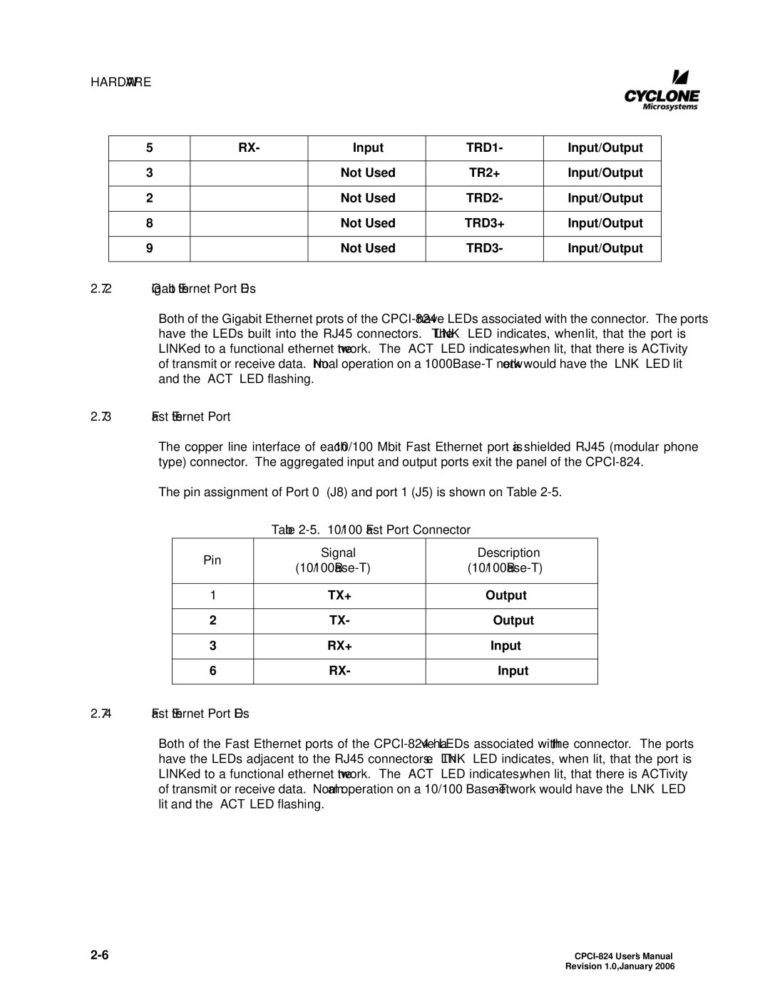
The copper line interface of each 10/100 Mbit Fast Ethernet port is a shielded RJ45 (modular phone type) connector. The aggregated input and output ports exit the panel of the CPCI-824.
The pin assignment of Port 0 (J8) and port 1 (J5) is shown on Table 2-5.
Table 2-5. 10/100 Fast Port Connector
| Pin | Signal | Description |
| (10/100Base-T) | (10/100Base-T) |
| |
| | | |
| 1 | TX+ | Output |
| | | |
| 2 | TX- | Output |
| | | |
| 3 | RX+ | Input |
| | | |
| 6 | RX- | Input |
| | | |
2.7.4Fast Ethernet Port LEDs
Both of the Fast Ethernet ports of the CPCI-824 have LEDs associated with the connector. The ports have the LEDs adjacent to the RJ45 connectors. The “LNK” LED indicates, when lit, that the port is LINKed to a functional ethernet network. The “ACT” LED indicates, when lit, that there is ACTivity of transmit or receive data. Normal operation on a 10/100 Base-T network would have the “LNK” LED lit and the “ACT” LED flashing.
2-6 | CPCI-824 User’s Manual |
| Revision 1.0, January 2006 |