PMC MODULE INTERFACE
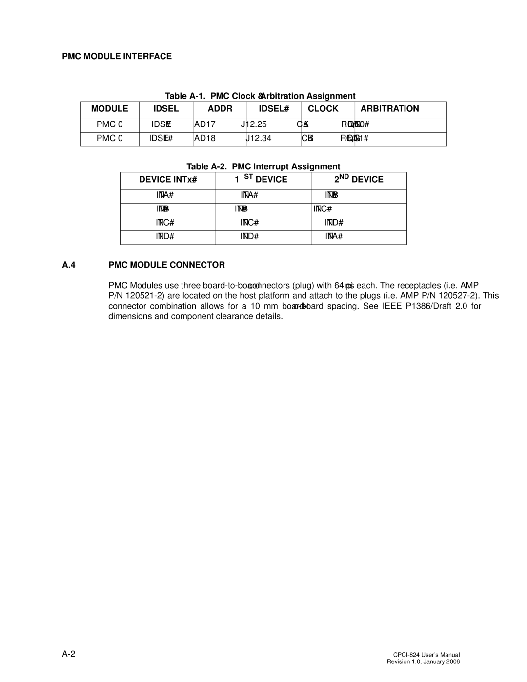
Table A-1. PMC Clock & Arbitration Assignment
MODULE | IDSEL | ADDR | IDSEL# | CLOCK | ARBITRATION |
| | | | | |
PMC 0 | IDSEL# | AD17 | J12.25 | CLKA | REQ0#,GNT0# |
| | | | | |
PMC 0 | IDSEL1# | AD18 | J12.34 | CLKB | REQ1#,GNT1# |
| | | | | |
Table A-2. PMC Interrupt Assignment
DEVICE INTx# | 1ST DEVICE | 2ND DEVICE |
INTA# | INTA# | INTB# |
| | |
INTB# | INTB# | INTC# |
| | |
INTC# | INTC# | INTD# |
| | |
INTD# | INTD# | INTA# |
| | |
A.4 PMC MODULE CONNECTOR
PMC Modules use three board-to-board connectors (plug) with 64 pins each. The receptacles (i.e. AMP P/N 120521-2) are located on the host platform and attach to the plugs (i.e. AMP P/N 120527-2). This connector combination allows for a 10 mm board-to-board spacing. See IEEE P1386/Draft 2.0 for dimensions and component clearance details.
A-2 | CPCI-824 User’s Manual |
| Revision 1.0, January 2006 |