C156-E224-01EN
MCJ3230SS OPTICAL DISK DRIVE PRODUCT MANUAL
Handling of This Manual
FOR SAFE OPERATION
Revision History
This page is intentionally left blank
Chapter 3 Installation Requirements
Chapter 2 Specifications
Chapter 5 Diagnostics and Maintenance
Chapter 6 Diagnostics and Maintenance
Conventions for Alert Messages
CONVENTIONS USED IN THIS MANUAL
Glossary
Acronyms and Abbreviations
Example
C156-E224-01EN
DISCLAIMER
Important Alert Items
Low temperature burns
Important Alert Messages
Device damage
Damage for data medium
Device Damage
Damage for disk medium
Eye inflammation
1. GENERAL DESCRIPTION 2. SPECIFICATIONS 3. INSTALLATION REQUIREMENTS
This manual OPTICAL DISK DRIVES MAINTENANCE MANUAL C156-F043
4. HOST INTERFACE 5. OPERATION AND CLEANING
6. DIAGNOSTICS AND MAINTENANCE 1. MAINTENANCE AND DIAGNOSIS
REFERENCED STANDARDS
Specifications
Contents
Preface
DISCLAIMER
Contents
Installation Requirements
Operation Confirmation and Preparation for Use after Installation
CHAPTER
SYNCHRONIZE CACHE command
CHAPTER 4 Host Interface
4.3.10 PREVENT/ALLOW MEDIUM REMOVAL command
CHAPTER 6 Diagnosis and Maintenance
CHAPTER 5 Operation and Cleaning
5.3.3 How to affix an index label on the MO cartridge
Optical Disk Cartridge Operation
……………………………………………………………………….GL-1
Glossary
Abbreviations
…….…………………………………………………………………AB-1
Figures
Illustrations
Revision number indication
C156-E224-01EN
Revision label
Default values in the read-write error recovery page
Tables
Variable values in the read-write error recovery page
Defect List Format of READ DEFECT DATA 10 command
PREVENT/ALLOW MEDIUM REMOVAL command
Defect list header of READ DEFECT DATA 10 command
RECEIVE DIAGNOSTIC RESULTS command
This page is intentionally left blank
CHAPTER 1 General Description
1.1.1 Performance
1.1 Features
1.1 Features
1.1.2 Reliability
1.1.4 Adaptability
1.1.3 Maintainability/operability
1.1.5 Interface
6 Defective block slipping
Figure 1.1 Outer view with panel Figure 1.2 Outer view without panel
1.2 Drive Configuration
1.2.1 Drive model
Figure 1.3 Optical disk drive configuration
1.2.2 Configuration
1.2.3 Mechanical sections
1.2.4 Control circuit section
Figure 1.4 Control circuit section block diagram
1-11
1.2 Drive Configuration
C156-E224-01EN
This page is intentionally left blank
2.1 Optical Disk Drive Specifications
CHAPTER 2 Specifications
2.1.1 Model and product number
Table 2.1 Model and order number
Table 2.2 Specifications 1 of
2.1.2 Drive specifications
2.1 Optical Disk Drive Specifications
Table 2.2 Specifications 2 of
Table 2.3 Environmental and power requirements 1 of
2.1.3 Environmental and power requirements
Table 2.3 Environmental and power requirements 2 of
2.1.5 Reliability
2.1.4 Error rate
Table 2.5 Recommended optical disk cartridge specifications
2.2 Optical Disk Cartridge Specifications
2.2.1 Recommended optical disk cartridge specifications
Figure 2.1 Optical disk cartridge
2.2.2 Optical disk cartridge
2.2.3 Disk specifications
Table 2.6 Disk specifications
Figure 2.2 Algorithms for alternate processing
2.3.1 Defect management schematic diagram
2.3 Defect Management
C156-E224-01EN
Figure 2.3 Example of alternate processing
2-12
3.1 Environmental Requirements
CHAPTER 3 Installation Requirements
3.1.1 Temperature measurement point
Installation Requirements
Figure 3.1 Surface temperature measurement points
IC power amp
IC controller
3.1.3 Air flow
3.1.2 Temperature requirements and measuring method
Table 3.1 Temperature requirements at measurement points
3.1.5 Air purity
3.1.4 Temperature rise under several conditions
Table 3.2 Temperature at each measuring point Reference
3.2 Mounting Requirements
3.2.1 External dimensions
Figure 3.2 Dimensions
C156-E224-01EN
Figure 3.3 Dimensions without panel
Unit mm
Figure 3.4 Installation directions
3.2.2 Installation direction
Figure 3.5 Centers of gravity
3.2.3 Centers of gravity
Figure 3.6 Mounting frame structure
3.2.4 Notes on mounting
P side
Figure 3.7 Service clearance
R side
Q side
Figure 3.8 Current waveform +5 VDC
3.3 Power Supply Requirements
Figure 3.9 Connector and terminal locations
3.4.1 Drive connectors
Figure 3.10 Location of setting terminal
3.4 Cable Connections
Figure 3.11 Shape of setting terminal
Table 3.3 Pin assignments
Table 3.4 Recommended components for connection
3.4.2 Cable connector specifications
Figure 3.12 SCSI bus connection modes
3.4.3 Connection Modes
c. Connecting more than one optical disk drive multi-host
Figure 3.13 SCSI bus connection modes
C156-E224-01EN
3-17
3.5.1 Default jumper settings
3.5 Settings
3.5.2 Setting terminal
Figure 3.14 Setting terminal CNH2
3.5 Settings
Table 3.6 SCSI terminating resistor mode
Table 3.7 Write cache mode setting
OPEN *1
Table 3.8 Spindle motor automatic stop mode setting
SHORT
Device damage
3.6 Notes on Drive Handling
3 Installation
Multiple-unit packing
Figure 3.15 Packing style
Single-unit packing
3.7.1 Checks before mounting the drive
3.7.2 Mounting procedure
3.7 Mounting
3.8 Cable Connections
3.9.1 Confirming initial operations
3.9 Operation Confirmation and Preparation for Use after Installation
3.9.2 Connection check
3.10 Dismounting Drive
This page is intentionally left blank
CHAPTER 4 Host Interface
4.1 Interface Connector
Figure 4.1 SCSI interface connector ODD side
Host Interface
Figure 4.2 SCSI interface connector cable side
4.1 Interface Connector
Table 4.1 SCSI interface connector pin assignments single-ended type
4.2 Various Processes
4.2.1 Reset response
4.2.2 Defective sector management
4.2.3 Automatic alternate sector assignment function
4.2.4.2 Read cache
4.2.4 Cache function
4.2.4.1 Data buffer
4.2.4.3 MO write cache
4.2.5 Power management function
4.2.6 Power mode
4.2.6.2 Pre-idle mode
4.2.6.1 Active mode
4.2.6.3 Idle mode
4.2.6.4 Standby mode
Figure 4.3 Power mode
4.2.6.6 Power mode transition
Active Reset
Idle
Table 4.2 LED indications
4.2.7 LED indications
Table 4.3 SCSI commands
4.3 SCSI Commands
Table 4.4 TEST UNIT READY command
4.3.1 TEST UNIT READY command
Table 4.5 INQUIRY command
4.3.2 INQUIRY
CmdQue
Table 4.6 INQUIRY command response data
Linked
4.3.4 MODE SELECT command
4.3.3 READ CAPACITY command
Table 4.7 READ CAPACITY command
Table 4.9 MODE SELECT command
Table 4.12 Mode parameter header
Table 4.10 Mode page codes
Table 4.11 Mode parameter list
Table 4.13 Block descriptor
Table 4.14 Mode page
Table 4.15 Read/write error recovery page
Default values in the read-write error recovery page
Table 4.16 Variable values in the read-write error recovery page
Table 4.18 Flexible disk page
Default values in the flexible disk page
Variable values in the flexible disk page
Table 4.21 Caching page
Table 4.24 Power condition page
Table 4.22 Variable values in the Caching Page
Table 4.23 Default values in the Caching Page
Verify control page
Table 4.25 Variable values in the Power condition page
Table 4.26 Default values in the Power condition page
Variable values in the Verify control page
Table 4.28 Verify mode
Default values in the Verify control page
Page control field
4.3.5 MODE SENSE command
Table 4.31 MODE SENSE command
Table 4.35 Block Descriptor
Table 4.33 Mode parameters
Table 4.34 Mode Parameter Header
Table 4.36 Mode Page
4.3.6 START/STOP UNIT command
Table 4.37 START/STOP UNIT command
Table 4.38 Start, stop, and eject processing
Table 4.39 RESERVE command
4.3.7 RESERVE command
4.3.9 REQUEST SENSE command
4.3.8 RELEASE command
Table 4.40 RELEASE command
Table 4.41 REQUEST SENSE command
Reserved 00h
Table 4.43 Error Code
Table 4.42 Request Sense Data
Table 4.45 Logical track address format
Table 4.44 Sense Key
NOT READY TO READY TRANSITION, MEDIUM MAY HAVE
Table 4.46 ASC and ASCQ definitions
ASCQ
Table 4.47 Format progress indication bytes
Table 4.49 Responses to Prevent, Allow, and Eject
4.3.10 PREVENT/ALLOW MEDIUM REMOVAL command
Table 4.48 PREVENT/ALLOW MEDIUM REMOVAL command
4.3.12 READ 10 command
4.3.11 READ 6 command
Table 4.50 CDB of READ 6 command
Table 4.51 READ 10 command
4.3.14 WRITE 6 command
4.3.13 VERIFY command
Table 4.52 VERIFY command
Table 4.53 CDB of WRITE 10 command
Table 4.54 WRITE 10 command
4.3.15 WRITE 10 command
Table 4.55 WRITE AND VERIFY command
4.3.16 WRITE AND VERIFY
4.3.18 SEEK 10 command
4.3.17 SEEK 6 command
Table 4.56 SEEK 6 command
Table 4.57 SEEK 10 command
4.3.20 SYNCHRONIZE CACHE command
4.3.19 ERASE command
Table 4.58 ERASE command
Table 4.59 SYNCHRONIZE CACHE command
Table 4.60 FORMAT UNIT command
4.3.21 FORMAT UNIT command
Table 4.61 FORMAT UNIT parameter list
Table 4.62 Defect List Header
Table 4.63 READ DEFECT DATA command
4.3.22 READ DEFECT DATA command
Table 4.64 Defect List Format of READ DEFECT DATA 10 command
Table 4.65 Defect list header of READ DEFECT DATA 10 command
4.3.24 RECEIVE DIAGNOSTIC RESULTS command
4.3.23 SEND DIAGNOSTIC command
Table 4.68 SEND DIAGNOSTIC command
Table 4.69 RECEIVE DIAGNOSTIC RESULTS command
Table 4.70 WRITE BUFFER command
4.3.25 WRITE BUFFER command
4.3.27 WRITE LONG command
4.3.26 READ LONG command
Table 4.71 READ LONG command
Table 4.72 WRITE LONG command
4.4.1 Message formats
4.4 SCSI Messages
4.4.2 Message types
Table 4.73 Types of messages provided by ODD
4.4 SCSI Messages
4.4.3 Message functions
6 MESSAGE REJECT message 07h I → T
REQ/ACK Offset =
Table 4.74 Transfer mode settings requested by INIT to ODD
Asynchronous transfer
4.5 Timing Rule
Table 4.75 Timing specifications 1 of
4.5 Timing Rule
Table 4.75 Timing specifications 2 of
Table 4.75 Timing specifications 3 of
Figure 4.4 BUS FREE phase
Table 4.76 FAST SCSI Timing specifications
C156-E224-01EN
Figure 4.5 ARBITRATION phase
4-50
Figure 4.6 SELECTION phase Figure 4.7 RESELECTION phase
C156-E224-01EN
Figure 4.8 Transfer in asynchronous mode
4-52
4-53
Figure 4.9 Transfer in FAST SCSI mode
C156-E224-01EN
C156-E224-01EN
Figure 4.10 ATTENTION condition
4-54
5.1 Operating Optical Disk Drive
CHAPTER 5 Operation and Cleaning
Figure 5.1 Optical disk drive front view with panel
5.1.1 Optical disk drive
5.1 Operating Optical Disk Drive
5.1.2 Note
5.1.3 Inserting cartridge
Shutter
Figure 5.2 Inserting cartridge
Inserting direction
Figure 5.3 Removing cartridge
5.1.4 Ejecting removing cartridge
Table 5.1 Head cleaner
5.2 Cleaning Drive
Figure 5.4 Optial disk cartridge
5.3 Optical Disk Cartridge Operation
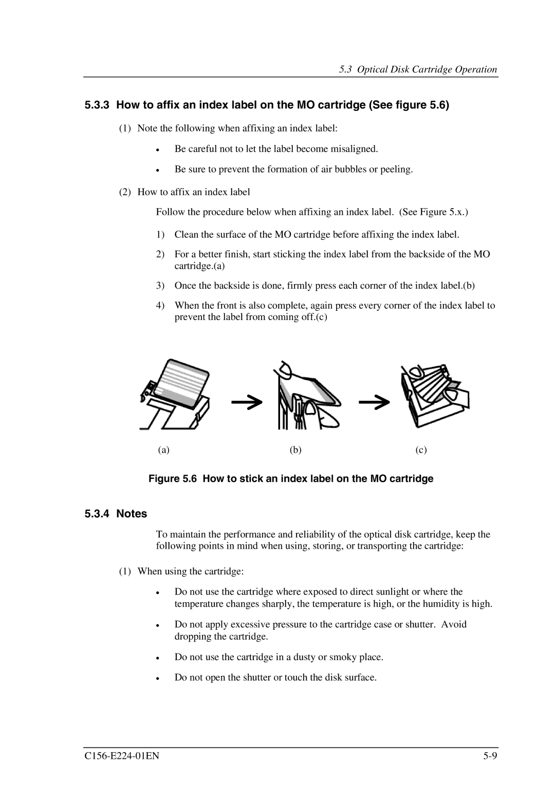
5.3.1 Optical disk cartridge
Figure 5.5 Write protect tab
5.3.2 Write protect tab
5.3.4 Notes
5.3.3 How to affix an index label on the MO cartridge See figure
Figure 5.6 How to stick an index label on the MO cartridge
2 When storing the cartridge
5.4.1 Cleaning tool
5.4 Cleaning Optical Disk Cartridge
Table 5.2 Cleaning kit
Table 5.3 Packed items cleaning kit
Figure 5.7 Cleaning procedure
5.4.2 Cleaning procedure
Figure 5.9 Cleaning procedure
Figure 5.8 Cleaning procedure
7 Turn the revolving knob, then wipe the disk surface Cleaning cloth
Figure 5.10 Cleaning procedure
6 Wipe the disk surface from the hub outward
5-14
Table 6.1 Self-diagnostic function
CHAPTER 6 Diagnosis and Maintenance
6.1 Diagnosis
6.1.1 Initial self-diagnosis
Diagnosis and Maintenance
6.1.2 Diagnostic command
6.1.3 Test program
Data loss
6.2 Maintenance Information
6.2.1 Maintenance requirements
Figure 6.2 Revision number indication
6.2.2 Revision number
Figure 6.1 Revision label
CDB Command Descriptor Block
Axial displacement
Command
Glossary
Error detection and correction
Error correction code
Recording power
Disk reference surface
GL-3
Status
C156-E224-01EN
This page is intentionally left blank
Acronyms and Abbreviations
ABORT message
Index
Fujitsu Internal Use Only
Index
RESELECTION phase
write cache feature
service system and repair
sector address format
SYNCHRONOUS DATA TRANSFER REQUEST message
10/F., Lincoln House, 979 Kings Road, Taikoo Place, Island
2 Julius Avenue Cnr Delhi Road North Ryde N.S.W
This page is intentionally left blank
FOR FUJITSU USE
READER’S COMMENT FORM