Installation Requirements
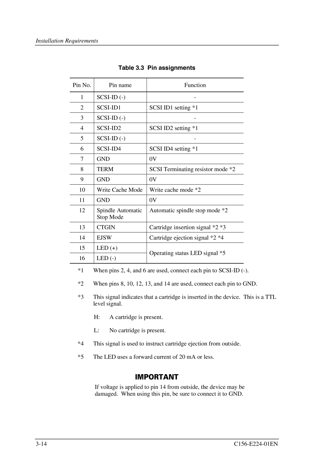
Table 3.3 Pin assignments
Pin No. | Pin name | Function | |
|
|
| |
1 | - | ||
|
|
| |
2 | SCSI ID1 setting *1 | ||
|
|
| |
3 | - | ||
|
|
| |
4 | SCSI ID2 setting *1 | ||
|
|
| |
5 | - | ||
|
|
| |
6 | SCSI ID4 setting *1 | ||
|
|
| |
7 | GND | 0V | |
|
|
| |
8 | TERM | SCSI Terminating resistor mode *2 | |
|
|
| |
9 | GND | 0V | |
|
|
| |
10 | Write Cache Mode | Write cache mode *2 | |
|
|
| |
11 | GND | 0V | |
|
|
| |
12 | Spindle Automatic | Automatic spindle stop mode *2 | |
| Stop Mode |
| |
|
|
| |
13 | CTGIN | Cartridge insertion signal *2 *3 | |
|
|
| |
14 | EJSW | Cartridge ejection signal *2 *4 | |
|
|
| |
15 | LED (+) | Operating status LED signal *5 | |
|
| ||
16 | LED | ||
| |||
|
|
|
*1 When pins 2, 4, and 6 are used, connect each pin to
*2 When pins 8, 10, 12, 13, and 14 are used, connect each pin to GND.
*3 This signal indicates that a cartridge is inserted in the device. This is a TTL level signal.
H:A cartridge is present.
L:No cartridge is present.
*4 This signal is used to instruct cartridge ejection from outside. *5 The LED uses a forward current of 20 mA or less.
If voltage is applied to pin 14 from outside, the device may be damaged. When using this pin, be sure to connect it to GND.
