Manuals
/
Fujitsu
/
Computer Equipment
/
Computer Drive
Fujitsu
MCJ3230SS
manual
Selection phase
Models:
MCJ3230SS
1
125
161
161
Download
161 pages
59.65 Kb
122
123
124
125
126
127
128
129
Specifications
Install
Error messages
Error rate
Standby timer
Dimension
Maintenance
Drive Configuration
Reset response
Send Diagnostic command
Page 125
Image 125
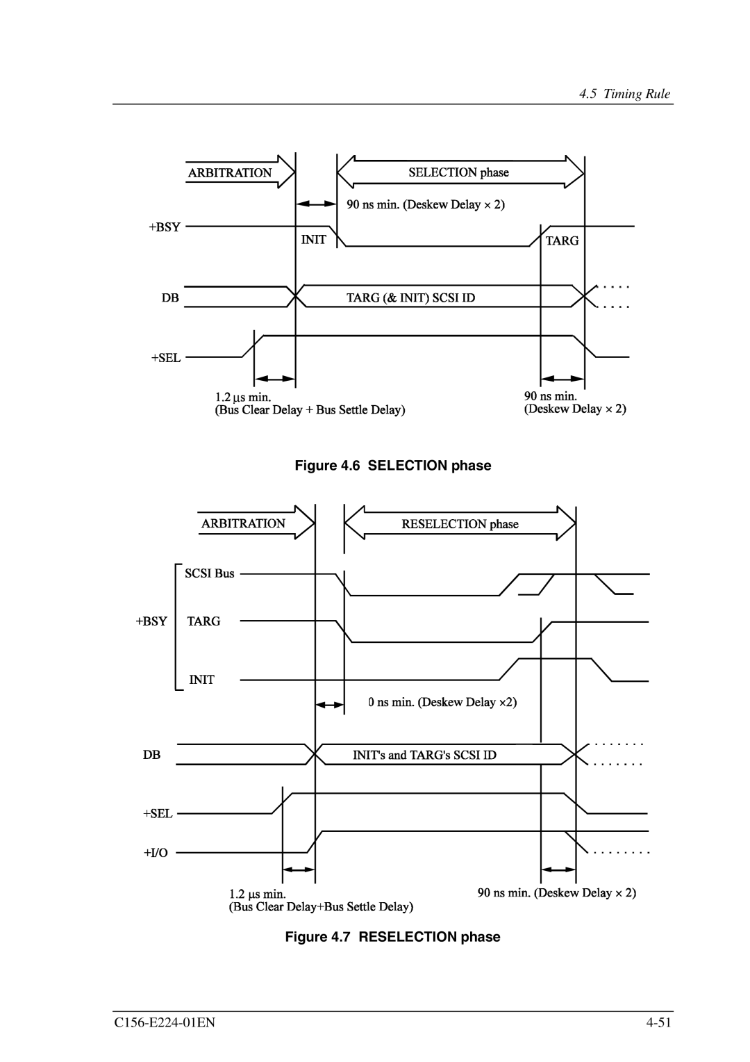
4.5 Timing Rule
∝
Figure 4.6 SELECTION phase
Figure 4.7 RESELECTION phase
C156-E224-01EN
4-51
Page 124
Page 126
Page 125
Image 125
Page 124
Page 126
Contents
MCJ3230SS Optical Disk Drive Product Manual
Handling of This Manual
For Safe Operation
Revision History
This page is intentionally left blank
Overview of Manual
Preface
Acronyms and Abbreviations
Conventions for Alert Messages
Glossary
Preface
Disclaimer
Important Alert Items
Low temperature burns
Important Alert Messages
Device damage
Damage for disk medium
Damage for data medium
Eye inflammation
Data loss
This manual
ISO/IEC *1
Scsi Ansi
ISO/IEC JTC1 *1
Fujitsu Limited
Contents
Installation Requirements
6.6
Host Interface
Diagnosis and Maintenance
Operation and Cleaning
C156-E224-01EN Xiii
Figures
Illustrations
Revision label Revision number indication
Tables
Power consumption in power save mode
C156-E224-01EN Xvii
This page is intentionally left blank
General Description
Performance
Features
Reliability
Features
Adaptability
Maintainability/operability
Interface
General Description
Drive model
Drive Configuration
Optical disk drive configuration
Configuration
Mechanical sections
Control circuit section
Control circuit section block diagram
Drive Configuration
This page is intentionally left blank
Optical Disk Drive Specifications
Specifications
Model and product number
Model and order number
Specifications 1
Drive specifications
Density
Specifications 2
Environmental and power requirements 1
Environmental and power requirements
Ietm
Environmental and power requirements 2
MTBF=
Error rate
Recommended optical disk cartridge specifications
Optical Disk Cartridge Specifications
Recommended optical disk cartridge specifications
Optical disk cartridge
Optical disk cartridge
Disk specifications
Disk specifications
Defect Management
Defect management schematic diagram
Example of alternate processing
Environmental Requirements
Installation Requirements
Temperature measurement point
Surface temperature measurement points
Air flow
Temperature requirements and measuring method
Temperature requirements at measurement points
Air purity
Temperature rise under several conditions
Temperature at each measuring point Reference
Mounting Requirements
External dimensions
Dimensions without panel
Installation directions
Installation direction
Centers of gravity
Centers of gravity
Mounting frame structure
Service clearance
Current waveform +5 VDC
Power Supply Requirements
Cable Connections
Drive connectors
11 Shape of setting terminal
Pin assignments
Recommended components for connection
Cable connector specifications
12 Scsi bus connection modes
Connection Modes
13 Scsi bus connection modes
Default jumper settings
Settings
Setting terminal
Scsi ID setting CNH2
Write cache mode setting
Scsi terminating resistor mode
Spindle motor automatic stop mode setting
General notes
Installation Requirements
15 Packing style
Checks before mounting the drive
Mounting procedure
Mounting
Cable Connections
Confirming initial operations
Connection check
Dismounting Drive
This page is intentionally left blank
Host Interface
Interface Connector
Scsi interface connector cable side
MSG SEL
Scsi interface connector pin assignments single-ended type
Various Processes
Reset response
Defective sector management
Automatic alternate sector assignment function
Read cache
Cache function
Data buffer
MO write cache
Power management function
Power mode
Pre-idle mode
Active mode
Idle mode
Standby mode
Power mode
Power mode transition
LED indications
LED indications
Scsi commands
Scsi Commands
Inquiry command
Test Unit Ready command
Test Unit Ready command
Inquiry command response data
Mode Select command
Read Capacity command
Read Capacity command
Mode Select command
12 Mode parameter header
10 Mode page codes
11 Mode parameter list
13 Block descriptor
14 Mode
15 Read/write error recovery
Default values in the read-write error recovery
16 Variable values in the read-write error recovery
18 Flexible disk
Variable values in the flexible disk
22 Variable values in the Caching
24 Power condition
21 Caching
Verify control
25 Variable values in the Power condition
26 Default values in the Power condition
Variable values in the Verify control
28 Verify mode
Default values in the Verify control
Control field
Mode Sense command
31 Mode Sense command
35 Block Descriptor
33 Mode parameters
34 Mode Parameter Header
36 Mode
START/STOP Unit command
37 START/STOP Unit command
38 Start, stop, and eject processing
39 Reserve command
Reserve command
Request Sense command
Release command
40 Release command
41 Request Sense command
42 Request Sense Data
43 Error Code
45 Logical track address format
44 Sense Key
46 ASC and Ascq definitions
47 Format progress indication bytes
48 PREVENT/ALLOW Medium Removal command
PREVENT/ALLOW Medium Removal command
49 Responses to Prevent, Allow, and Eject
Sense KEY
Read 10 command
Read 6 command
50 CDB of Read 6 command
51 Read 10 command
Write 6 command
Verify command
52 Verify command
53 CDB of Write 10 command
55 Write and Verify command
Write 10 command
54 Write 10 command
Seek 10 command
Seek 6 command
56 Seek 6 command
57 Seek 10 command
Synchronize Cache command
Erase command
58 Erase command
59 Synchronize Cache command
60 Format Unit command
Format Unit command
61 Format Unit parameter list
62 Defect List Header
63 Read Defect Data command
Read Defect Data command
64 Defect List Format of Read Defect Data 10 command
65 Defect list header of Read Defect Data 10 command
Receive Diagnostic Results command
Send Diagnostic command
Diml
Write Buffer command
70 Write Buffer command
Write Long command
Read Long command
71 Read Long command
72 Write Long command
Message formats
Scsi Messages
Message types
73 Types of messages provided by ODD
Message functions
LUN
74 Transfer mode settings requested by Init to ODD
Timing Rule
75 Timing specifications 1
75 Timing specifications 2
75 Timing specifications 3
BUS Free phase
76 Fast Scsi Timing specifications
Arbitration phase
Selection phase
Transfer in asynchronous mode
Transfer in Fast Scsi mode
10 Attention condition
Operating Optical Disk Drive
Operation and Cleaning
Optical disk drive front view with panel
Optical disk drive
Operating Optical Disk Drive
Inserting cartridge
Inserting cartridge
Removing cartridge
Ejecting removing cartridge
Head cleaner
Cleaning Drive
Optial disk cartridge
Optical Disk Cartridge Operation
Write protect tab
Write protect tab
How to stick an index label on the MO cartridge
How to affix an index label on the MO cartridge See figure
Operation and Cleaning
Cleaning tool
Cleaning Optical Disk Cartridge
Cleaning kit
Packed items cleaning kit
Cleaning procedure
Cleaning procedure
Cleaning procedure
10 Cleaning procedure
Self-diagnostic function
Diagnosis and Maintenance
Diagnosis
Initial self-diagnosis
Test program
Diagnostic command
Maintenance requirements
Maintenance Information
REV. no
Revision number
Glossary
Error detection and correction
Error correction code
Recording power
Disk reference surface
Status
This page is intentionally left blank
Acronyms and Abbreviations
ODF
ODD
OEM
PCA
Index
Index
Fujitsu Internal Use Only Index
Write and Verify command
Fujitsu Limited
This page is intentionally left blank
MCJ3230SS Optical Disk
READER’S Comment Form
Top
Page
Image
Contents