CY2291
Pinouts
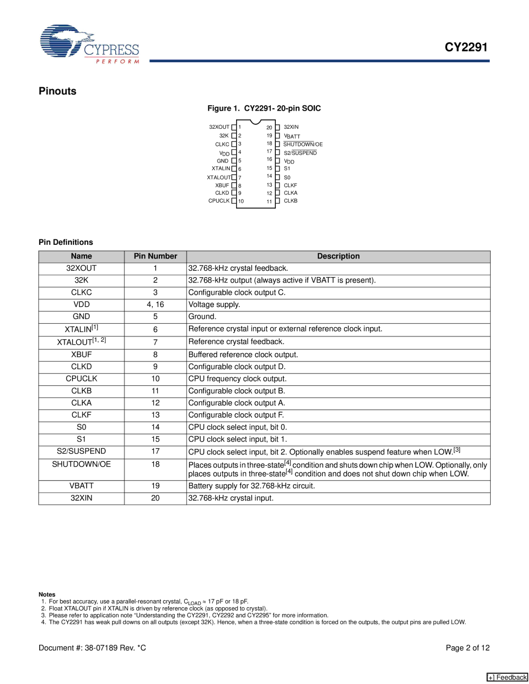
Figure 1. CY2291- | |||
32XOUT | 1 | 20 | 32XIN |
32K | 2 | 19 | VBATT |
CLKC | 3 | 18 | SHUTDOWN/OE |
VDD | 4 | 17 | S2/SUSPEND |
GND | 5 | 16 | VDD |
XTALIN | 6 | 15 | S1 |
XTALOUT | 7 | 14 | S0 |
XBUF | 8 | 13 | CLKF |
CLKD | 9 | 12 | CLKA |
CPUCLK | 10 | 11 | CLKB |
Pin Definitions
Name | Pin Number | Description |
32XOUT | 1 | |
|
|
|
32K | 2 | |
|
|
|
CLKC | 3 | Configurable clock output C. |
|
|
|
VDD | 4, 16 | Voltage supply. |
|
|
|
GND | 5 | Ground. |
|
|
|
XTALIN[1] | 6 | Reference crystal input or external reference clock input. |
XTALOUT[1, 2] | 7 | Reference crystal feedback. |
XBUF | 8 | Buffered reference clock output. |
|
|
|
CLKD | 9 | Configurable clock output D. |
|
|
|
CPUCLK | 10 | CPU frequency clock output. |
|
|
|
CLKB | 11 | Configurable clock output B. |
|
|
|
CLKA | 12 | Configurable clock output A. |
|
|
|
CLKF | 13 | Configurable clock output F. |
|
|
|
S0 | 14 | CPU clock select input, bit 0. |
|
|
|
S1 | 15 | CPU clock select input, bit 1. |
|
|
|
S2/SUSPEND | 17 | CPU clock select input, bit 2. Optionally enables suspend feature when LOW.[3] |
SHUTDOWN/OE | 18 | Places outputs in |
|
| places outputs in |
VBATT | 19 | Battery supply for |
|
|
|
32XIN | 20 |
|
|
|
|
Notes
1.For best accuracy, use a
2.Float XTALOUT pin if XTALIN is driven by reference clock (as opposed to crystal).
3.Please refer to application note “Understanding the CY2291, CY2292 and CY2295” for more information.
4.The CY2291 has weak pull downs on all outputs (except 32K). Hence, when a
Document #: | Page 2 of 12 |
[+] Feedback