CY62146ESL MoBL→
Pin Configuration
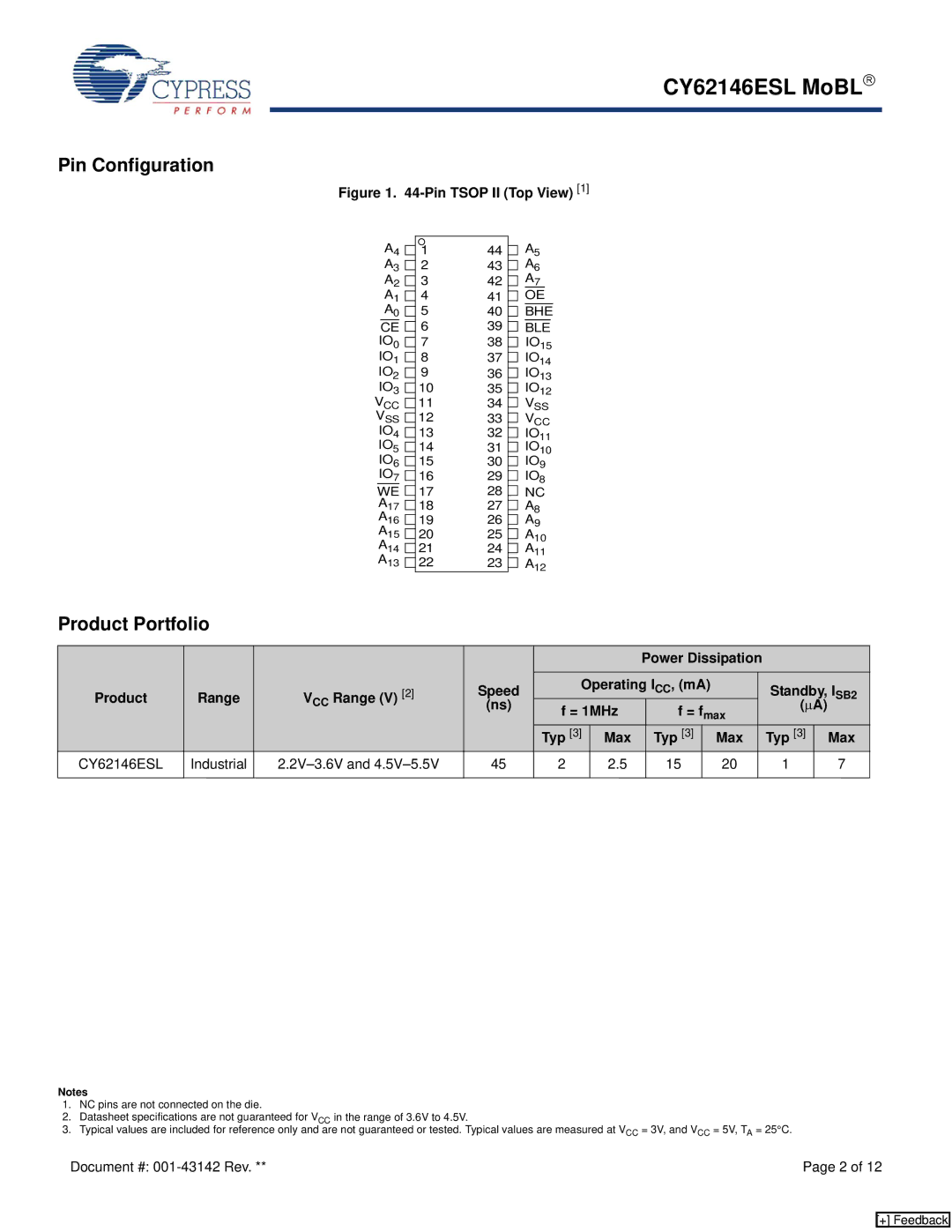
Figure 1. 44-Pin TSOP II (Top View) [1]
A4 ![]() A3
A3 ![]() A2
A2 ![]() A1
A1 ![]() A0
A0 ![]()
CE ![]() IO0
IO0 ![]() IO1
IO1 ![]() IO2
IO2 ![]() IO3
IO3 ![]()
VCC ![]() VSS
VSS ![]()
IO4 ![]()
IO5 ![]() IO6
IO6 ![]() IO7
IO7 ![]()
WE ![]()
A17
A16
A15 ![]()
A14
A13
144 ![]() A5
A5
243 ![]() A6
A6
342 ![]() A7
A7
441 ![]() OE
OE
540 ![]() BHE
BHE
639 ![]() BLE
BLE
738 ![]() IO15
IO15
837 ![]() IO14
IO14
936 ![]() IO13
IO13
1035 ![]() IO12
IO12
1134 ![]() VSS
VSS
1233 ![]() VCC
VCC
1332 ![]() IO11
IO11
1431 ![]() IO10
IO10
1530 ![]() IO9
IO9
1629 ![]() IO8
IO8
1728 ![]() NC
NC
1827 ![]() A8
A8
1926 ![]() A9
A9
2025 ![]() A10
A10
2124 ![]() A11
A11
2223 ![]() A12
A12
Product Portfolio
|
|
|
|
|
|
| Power Dissipation |
|
|
|
| |||
Product | Range | VCC Range (V) | [2] | Speed | Operating ICC, (mA) |
|
| Standby, I | SB2 | |||||
| (ns) | f = 1MHz | f = fmax |
| (μA) |
| ||||||||
|
|
|
|
|
|
|
|
|
| |||||
|
|
|
|
| Typ [3] | Max | Typ [3] |
| Max |
| Typ [3] |
| Max | |
CY62146ESL | Industrial |
| 45 | 2 | 2.5 | 15 |
| 20 |
| 1 |
|
| 7 | |
|
|
|
|
|
|
|
|
|
|
|
|
|
|
|
Notes
1.NC pins are not connected on the die.
2.Datasheet specifications are not guaranteed for VCC in the range of 3.6V to 4.5V.
3.Typical values are included for reference only and are not guaranteed or tested. Typical values are measured at VCC = 3V, and VCC = 5V, TA = 25°C.
Document #: | Page 2 of 12 |
[+] Feedback