
CY62157CV33, CY62157CV30 specifications
The Cypress CY62157CV30 and CY62157CV33 are high-performance synchronous static RAMs (SRAMs) designed for a wide range of applications in data storage and processing. These devices are notable for their speed, low power consumption, and versatility, making them ideal for use in systems where quick data access and high reliability are essential.One of the main features of the CY62157CV30 and CY62157CV33 is their advanced synchronous operation. These SRAMs support a clock frequency of up to 100 MHz, allowing for high-speed data access and efficient performance in time-critical applications. With a 16K x 8-bit memory organization, these devices provide ample storage capacity, suitable for various applications ranging from telecommunications to consumer electronics.
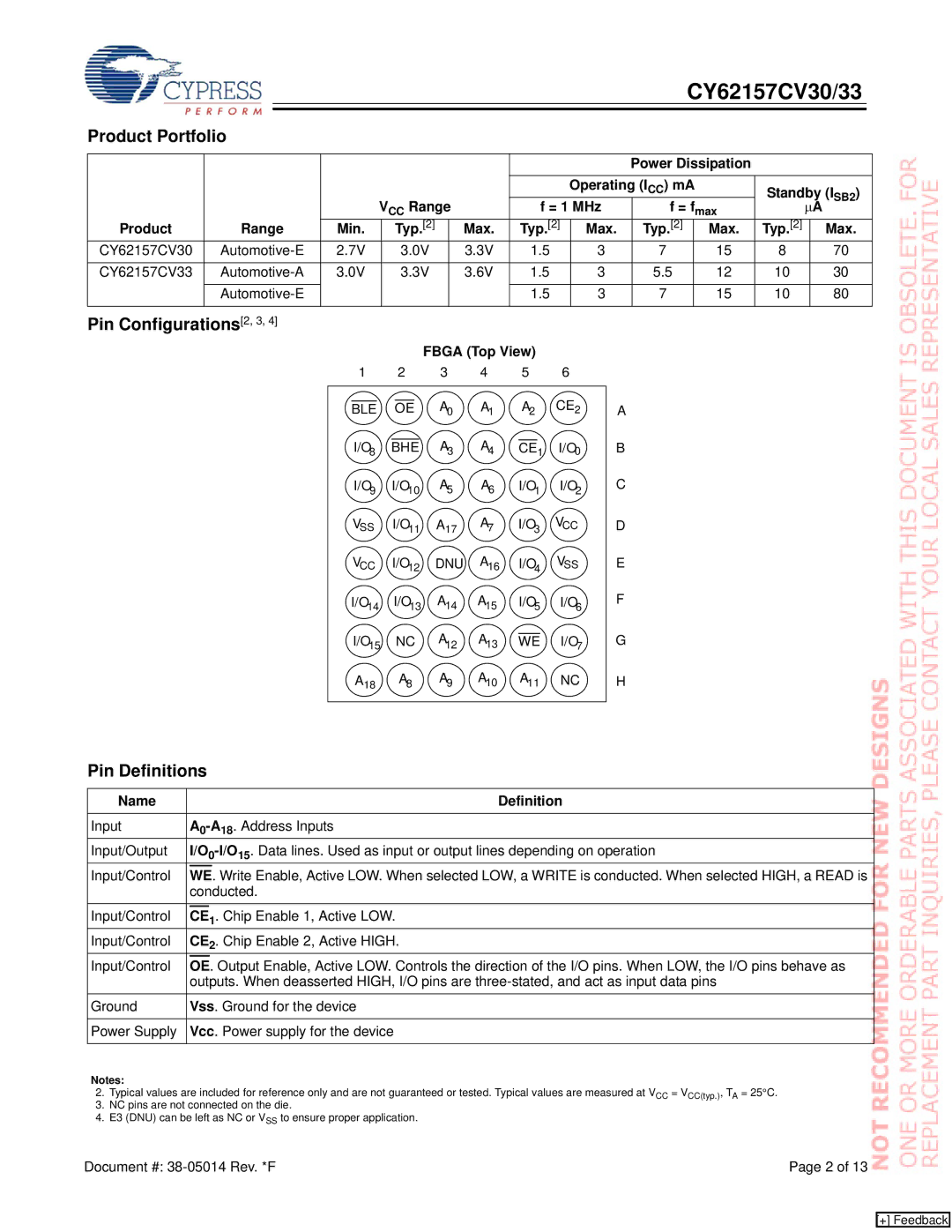
The CY62157CV30 and CY62157CV33 utilize a 3.0V to 3.6V operating voltage range, making them well-suited for low-voltage applications. This low-voltage operation contributes to reduced power consumption, allowing for longer battery life in portable devices. The SRAMs are also designed with a low standby current, further enhancing their efficiency and making them optimal for systems that require prolonged periods of inactivity without significant power drain.
Another significant characteristic of these SRAM devices is their compatibility with various standard bus protocols, including asynchronous and synchronous data transfer methods. This adaptability ensures that they can be seamlessly integrated into different system architectures, offering designers flexibility in their hardware configurations.
The CY62157CV30 and CY62157CV33 feature a simple interface that allows for easy control and management of memory operations. They support both read and write operations and can be utilized in a variety of configurations depending on the system requirements. Additionally, these SRAMs provide excellent data retention characteristics, ensuring reliable data storage even in the event of power loss.
In summary, the Cypress CY62157CV30 and CY62157CV33 synchronous SRAMs offer a compelling combination of high speed, low power consumption, and adaptability. Their advanced features and technologies make them suitable for diverse applications in industries such as automotive, telecommunications, and consumer electronics. With their impressive performance characteristics, these SRAMs continue to meet the growing demands for efficient and reliable memory solutions in modern electronic systems.