
CY62157EV18 specifications
The Cypress CY62157EV18 is a highly advanced static random-access memory (SRAM) chip that has garnered significant attention in the embedded systems and high-speed applications space due to its innovative features and reliable performance. This memory device is designed to meet the rigorous demands of modern electronics by providing fast access speeds and low power consumption.One of the main features of the CY62157EV18 is its high-density configuration, which offers a substantial memory capacity of 1 megabit (Mb). This capacity is often ideal for applications that require significant data storage without occupying too much physical space on the printed circuit board. The chip uses a 3.3V memory architecture, which enables compatibility with various voltage levels, making it versatile across different systems.
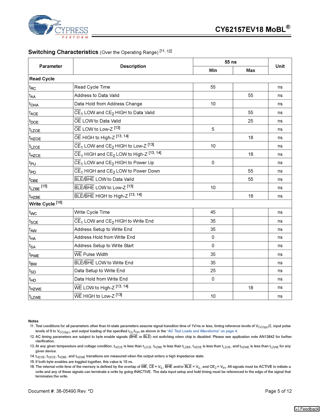
The device's access time is another standout characteristic, boasting a read access time of 10 to 15 nanoseconds. This incredibly fast access time allows for quicker data retrieval, which is crucial for real-time applications such as telecommunications, automotive electronics, and consumer devices. The design incorporates an improved write cycle time of 15 nanoseconds, ensuring that data can be written with minimal delay, further enhancing system performance.
Incorporating advanced CMOS technology, the CY62157EV18 achieves low power consumption while maintaining high-speed performance. It features a standby current of only 0.5 µA under a full ambient temperature range, which is particularly beneficial for battery-powered devices that demand energy efficiency. Additionally, with a wide operating temperature range from -40°C to 125°C, this memory chip is well-suited for industrial and automotive environments, where extreme temperatures can be a concern.
The device also includes full support for asynchronous SRAM operation, allowing for flexible interfacing with various microcontrollers and digital signal processors. With a simple interface that facilitates easy integration into existing designs, the CY62157EV18 offers designers the flexibility they need.
In conclusion, the Cypress CY62157EV18 is characterized by its high density, fast access speeds, low power consumption, and compatibility with a wide range of applications. Its array of features makes it an ideal choice for engineers looking to enhance performance in systems requiring reliable and efficient memory solutions. Whether in consumer electronics, automotive applications, or industrial controls, this SRAM chip continues to be a preferred option among developers seeking both performance and efficiency.