CY7C024AV/024BV/025AV/026AV
CY7C0241AV/0251AV/036AV
Maximum Ratings
Exceeding maximum ratings[14] may shorten the useful life of the device. User guidelines are not tested.
Storage Temperature | |
Ambient Temperature with |
|
Power Applied | |
Supply Voltage to Ground Potential | |
DC Voltage Applied to |
|
Outputs in |
DC Input Voltage[15] | |||
Output Current into Outputs (LOW) | 20 mA | ||
Static Discharge Voltage | > 2001V | ||
|
| > 200 mA | |
Operating Range |
|
| |
|
|
| |
Range | Ambient Temperature | VCC | |
Commercial | 0°C to +70°C |
| 3.3V ± 300 mV |
|
|
|
|
Industrial[16] |
| 3.3V ± 300 mV | |
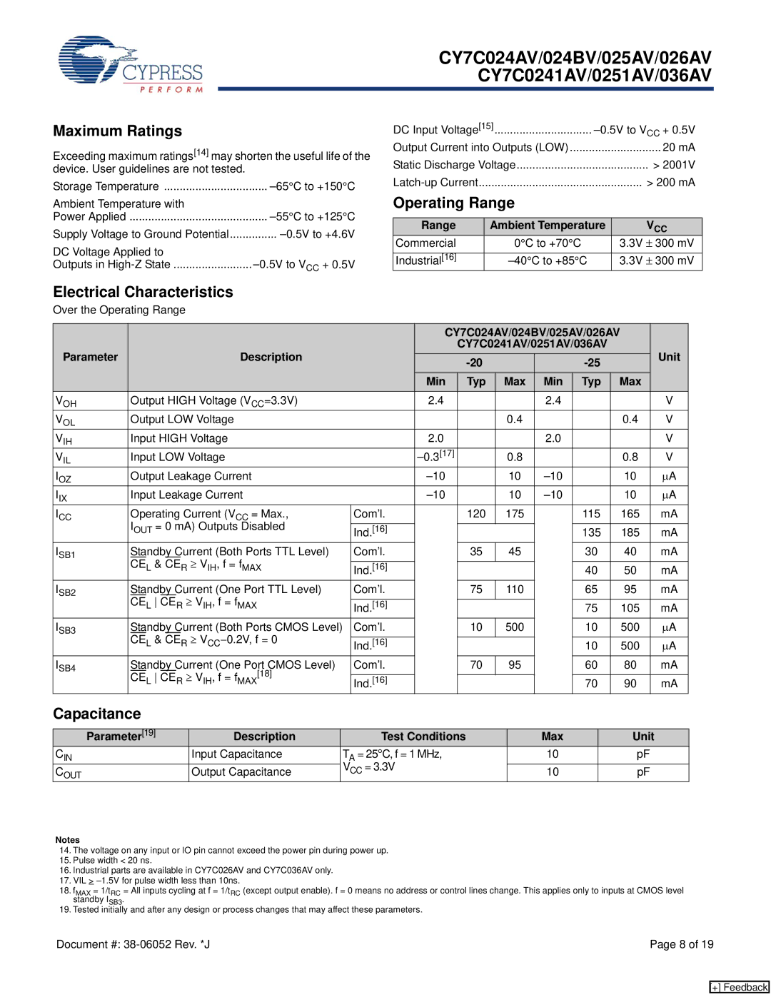
Electrical Characteristics
Over the Operating Range
|
|
| CY7C024AV/024BV/025AV/026AV |
| |||||
Parameter | Description |
|
| CY7C0241AV/0251AV/036AV |
| Unit | |||
|
|
|
|
| |||||
|
|
|
|
|
|
|
| ||
|
|
| Min | Typ | Max | Min | Typ | Max |
|
VOH | Output HIGH Voltage (VCC=3.3V) |
| 2.4 |
|
| 2.4 |
|
| V |
VOL | Output LOW Voltage |
|
|
| 0.4 |
|
| 0.4 | V |
VIH | Input HIGH Voltage |
| 2.0 |
|
| 2.0 |
|
| V |
VIL | Input LOW Voltage |
|
| 0.8 |
|
| 0.8 | V | |
IOZ | Output Leakage Current |
|
| 10 |
| 10 | μA | ||
IIX | Input Leakage Current |
|
| 10 |
| 10 | μA | ||
ICC | Operating Current (VCC = Max., | Com’l. |
| 120 | 175 |
| 115 | 165 | mA |
| IOUT = 0 mA) Outputs Disabled |
|
|
|
|
|
|
|
|
| Ind.[16] |
|
|
|
| 135 | 185 | mA | |
ISB1 | Standby Current (Both Ports TTL Level) | Com’l. |
| 35 | 45 |
| 30 | 40 | mA |
| CEL & CER ≥ VIH, f = fMAX |
|
|
|
|
|
|
|
|
| Ind.[16] |
|
|
|
| 40 | 50 | mA | |
ISB2 | Standby Current (One Port TTL Level) | Com’l. |
| 75 | 110 |
| 65 | 95 | mA |
| CEL CER ≥ VIH, f = fMAX |
|
|
|
|
|
|
|
|
| Ind.[16] |
|
|
|
| 75 | 105 | mA | |
ISB3 | Standby Current (Both Ports CMOS Level) | Com’l. |
| 10 | 500 |
| 10 | 500 | μA |
| CEL & CER ≥ VCC−0.2V, f = 0 |
|
|
|
|
|
|
|
|
| Ind.[16] |
|
|
|
| 10 | 500 | μA | |
ISB4 | Standby Current (One Port CMOS Level) | Com’l. |
| 70 | 95 |
| 60 | 80 | mA |
| CEL CER ≥ VIH, f = fMAX[18] |
|
|
|
|
|
|
|
|
| Ind.[16] |
|
|
|
| 70 | 90 | mA | |
Capacitance
Parameter[19] | Description | Test Conditions | Max | Unit |
CIN | Input Capacitance | TA = 25°C, f = 1 MHz, | 10 | pF |
|
| VCC = 3.3V |
|
|
COUT | Output Capacitance | 10 | pF |
Notes
14.The voltage on any input or IO pin cannot exceed the power pin during power up.
15.Pulse width < 20 ns.
16.Industrial parts are available in CY7C026AV and CY7C036AV only.
17.VIL >
18.fMAX = 1/tRC = All inputs cycling at f = 1/tRC (except output enable). f = 0 means no address or control lines change. This applies only to inputs at CMOS level standby ISB3.
19.Tested initially and after any design or process changes that may affect these parameters.
Document #: | Page 8 of 19 |
[+] Feedback