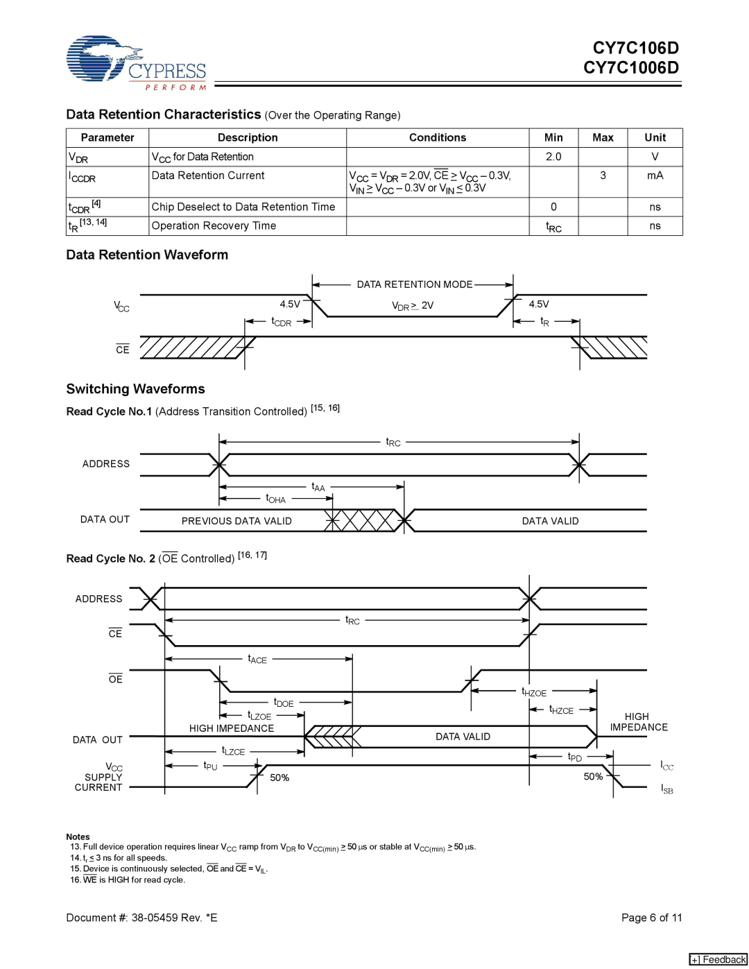
CY7C1006D, CY7C106D specifications
Cypress Semiconductor, a leader in providing advanced memory and storage solutions, offers a range of high-performance SRAM products. Among these, the CY7C106D and CY7C1006D stand out as robust choices for various applications that require speed and reliability.The CY7C106D is a 1 Megabit static RAM organized as 128K words by 8 bits. This SRAM is known for its high-speed performance, operating at access times as low as 10 nanoseconds, which makes it suitable for applications where quick data retrieval is crucial. Additionally, it features a range of voltage options, operating efficiently at 2.7V to 5.5V, allowing for flexibility in system design.
On the other hand, the CY7C1006D is a 256-Kbit static RAM organized as 32K words by 8 bits. Similarly, it showcases access times of up to 10 nanoseconds, ensuring a fast read and write capability. Both devices support asynchronous operations, meaning they don’t require clock cycles, further enhancing their speed in operations crucial for real-time applications.
Both the CY7C106D and CY7C1006D utilize advanced CMOS technology, which not only contributes to their low power consumption but also increases reliability and performance in data retention. The low standby power makes these SRAMs ideal for handheld and battery-operated devices, where power efficiency is paramount.
Another significant feature of these SRAM devices is their simple interfacing capabilities. They can be easily integrated into various electronic systems, whether in embedded systems, communications, networking, or industrial applications. Their straightforward pin configurations enable rapid design and implementation into existing system architectures.
In terms of reliability, Cypress SRAMs are consistent across temperature ranges, ensuring that the performance remains stable even in challenging operating conditions. With endurance ratings favoring frequent read/write cycles, they are well-suited for high-demand applications such as caching and buffering.
In summary, the CY7C106D and CY7C1006D SRAMs from Cypress represent a compelling combination of speed, flexibility, and low power consumption. Their advanced characteristics and technologies make them ideal for a wide array of applications, meeting the high-performance requirements of modern electronic systems while ensuring durability and ease of integration. These SRAMs are a solid choice for designers looking to enhance the reliability and efficiency of their memory solutions.

