STK14CA8
AC Test Conditions
Input Pulse Levels |
|
| 0V to 3V |
|
|
|
|
|
|
|
|
|
| ||||||||||
Input Rise and Fall Times |
|
|
| ≤ 5 ns |
|
|
|
|
|
|
|
|
|
| |||||||||
Input and Output Timing Reference Levels |
|
|
|
| 1.5V |
|
|
|
|
|
|
|
|
|
| ||||||||
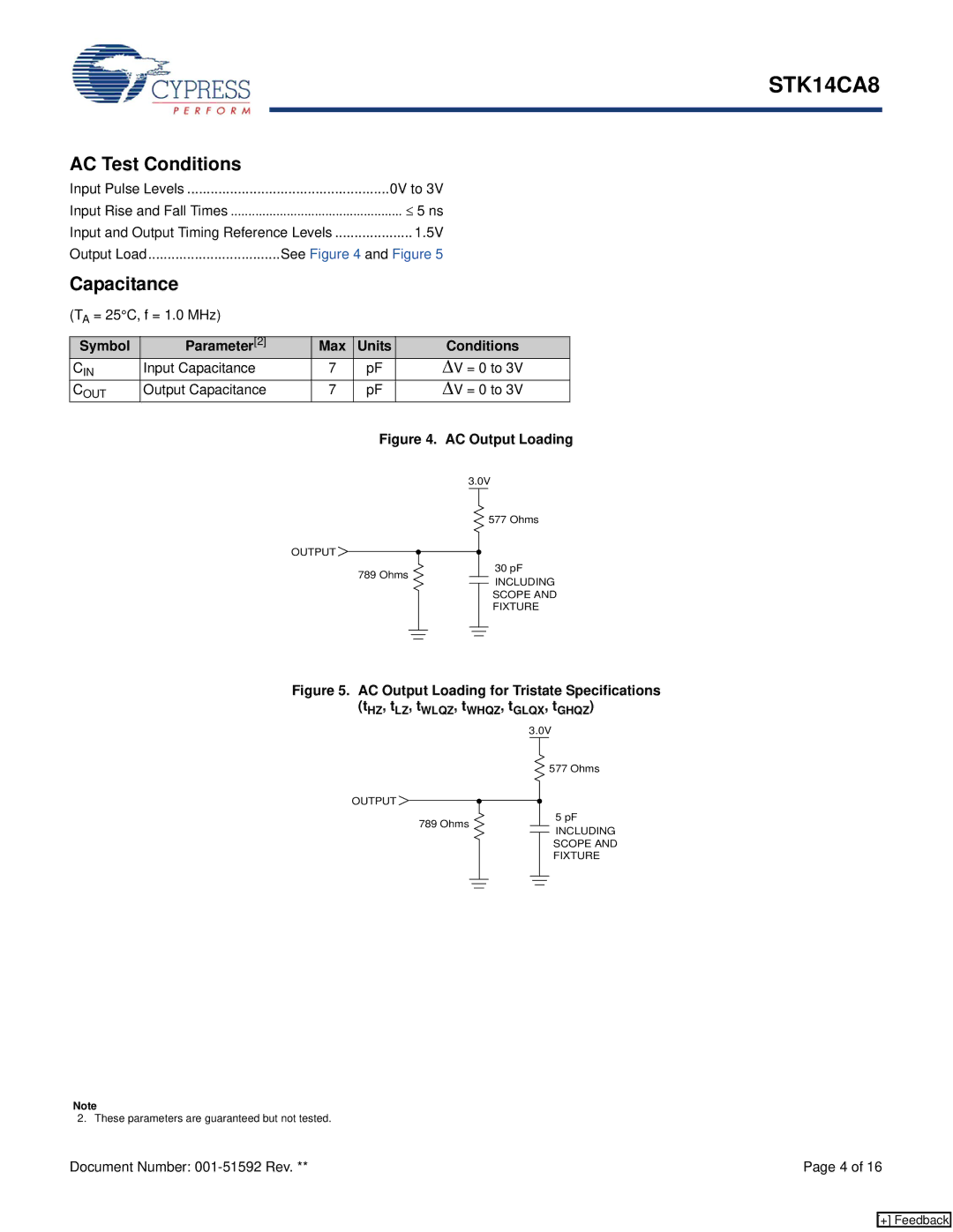
Output Load | See Figure 4 and Figure 5 |
|
|
|
|
|
|
|
|
|
| ||||||||||||
Capacitance |
|
|
|
|
|
|
|
|
|
|
|
|
|
|
|
|
|
|
|
|
|
| |
(TA = 25°C, f = 1.0 MHz) |
|
|
|
|
|
|
|
|
|
|
|
|
|
|
|
|
|
|
|
|
|
| |
|
|
|
|
|
|
|
|
|
|
|
|
|
|
|
|
|
|
|
|
|
|
|
|
Symbol | Parameter[2] |
| Max | Units |
|
|
|
|
|
|
|
| Conditions |
| |||||||||
CIN | Input Capacitance |
| 7 |
| pF |
|
|
|
|
|
|
| ΔV = 0 to 3V |
| |||||||||
COUT | Output Capacitance |
| 7 |
| pF |
|
|
|
|
|
|
| ΔV = 0 to 3V |
| |||||||||
|
|
|
|
| Figure 4. AC Output Loading | ||||||||||||||||||
|
|
|
|
|
|
|
|
|
|
|
|
|
| 3.0V | |||||||||
|
|
|
|
|
|
|
|
|
|
|
|
|
|
|
|
|
|
|
|
| 577 Ohms | ||
|
|
|
|
|
|
|
|
|
|
|
|
|
|
|
|
|
|
|
|
| |||
|
| OUTPUT |
|
|
|
|
|
|
|
|
|
|
|
|
|
|
|
|
|
| 30 pF | ||
|
|
|
|
|
|
|
|
|
|
|
|
|
|
|
|
|
|
|
| ||||
|
|
|
|
|
|
|
|
|
|
|
|
|
|
|
|
|
|
|
| ||||
|
|
|
|
|
|
|
|
|
|
|
|
|
|
|
|
|
|
|
|
|
| ||
|
|
|
|
| 789 Ohms |
|
|
|
|
|
|
|
| ||||||||||
|
|
|
|
|
|
|
|
|
|
|
|
| INCLUDING | ||||||||||
|
|
|
|
|
|
|
|
|
|
|
|
|
|
|
|
|
|
|
|
|
| SCOPE AND | |
|
|
|
|
|
|
|
|
|
|
|
|
|
|
|
|
|
|
|
|
|
| FIXTURE | |
|
|
|
|
|
|
|
|
|
|
|
|
|
|
|
|
|
|
|
|
|
|
|
|
|
|
|
|
|
|
|
|
|
|
|
|
|
|
|
|
|
|
|
|
|
|
|
|
|
|
|
|
|
|
|
|
|
|
|
|
|
|
|
|
|
|
|
|
|
|
|
|
|
|
|
|
|
|
|
|
|
|
|
|
|
|
|
|
|
|
|
|
|
|
|
|
Figure 5. AC Output Loading for Tristate Specifications
(tHZ, tLZ, tWLQZ, tWHQZ, tGLQX, tGHQZ)
|
|
|
|
|
|
| 3.0V | ||||||||
|
|
|
|
|
|
|
|
|
|
|
|
|
| 577 Ohms | |
|
|
|
|
|
|
|
|
|
|
|
|
|
| ||
OUTPUT |
|
|
|
|
|
|
|
|
|
|
|
|
|
| 5 pF |
|
|
|
|
|
|
|
|
|
|
|
|
|
| ||
789 Ohms |
|
|
|
|
|
|
|
|
|
|
|
|
| ||
|
|
|
|
|
|
|
|
|
|
|
|
|
| ||
|
|
|
|
|
|
|
|
|
|
|
|
|
| ||
|
|
|
|
|
|
|
|
|
|
|
|
|
| INCLUDING | |
|
|
|
|
|
|
|
|
|
|
|
|
|
|
| SCOPE AND |
|
|
|
|
|
|
|
|
|
|
|
|
|
|
| FIXTURE |
|
|
|
|
|
|
|
|
|
|
|
|
|
|
|
|
|
|
|
|
|
|
|
|
|
|
|
|
|
|
|
|
|
|
|
|
|
|
|
|
|
|
|
|
|
|
|
|
Note
2. These parameters are guaranteed but not tested.
Document Number: | Page 4 of 16 |
[+] Feedback