Z9973
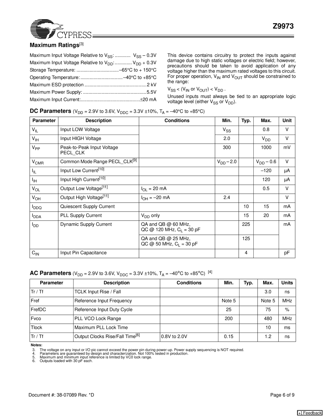
Maximum Ratings[3]
Maximum Input Voltage Relative to VSS: | ............ VSS – 0.3V |
Maximum Input Voltage Relative to VDD: | ............. VDD + 0.3V |
Storage Temperature: | |
Operating Temperature: | |
Maximum ESD protection | 2 kV |
Maximum Power Supply: | 5.5V |
Maximum Input Current: | ± 20 mA |
DC Parameters (VDD = 2.9V to 3.6V, VDDC = 3.3V ±10%, TA
This device contains circuitry to protect the inputs against damage due to high static voltages or electric field; however, precautions should be taken to avoid application of any voltage higher than the maximum rated voltages to this circuit. For proper operation, VIN and VOUT should be constrained to the range:
VSS < (VIN or VOUT) < VDD .
Unused inputs must always be tied to an appropriate logic voltage level (either VSS or VDD).
=
Parameter |
|
| Description |
|
|
|
|
|
| Conditions |
| Min. | Typ. |
| Max. | Unit |
|
|
|
|
|
|
|
|
|
|
|
|
|
|
|
| |
VIL | Input LOW Voltage |
|
|
|
|
|
|
|
| VSS |
| 0.8 | V | |||
VIH | Input HIGH Voltage |
|
|
|
|
|
|
| 2.0 |
|
| VDD | V | |||
VPP |
|
|
|
|
|
|
| 300 |
| 1000 | mV | |||||
| PECL_CLK |
|
|
|
|
|
|
|
|
|
|
|
|
| ||
|
|
|
|
|
|
|
|
|
|
|
|
|
| |||
VCMR | Common Mode Range PECL_CLK[9] |
|
|
|
|
| VDD – 2.0 |
| VDD – 0.6 | V | ||||||
IIL | Input Low Current[10] |
|
|
|
|
|
|
|
|
|
|
| µA | |||
IIH | Input High Current[10] |
|
|
|
|
|
|
|
|
|
| 120 | µA | |||
VOL | Output Low Voltage[11] |
|
|
| IOL = 20 mA |
|
|
| 0.5 | V | ||||||
VOH | Output High Voltage[11] |
|
|
| IOH = | 2.4 |
|
|
| V | ||||||
IDDQ | Quiescent Supply Current |
|
|
|
|
|
|
|
|
| 10 | 15 | mA | |||
IDDA | PLL Supply Current |
|
|
| VDD only |
|
|
|
| 15 | 20 | mA | ||||
IDD | Dynamic Supply Current |
|
|
| QA and QB @ 60 MHz, |
|
| 225 |
|
| mA | |||||
|
|
|
|
|
|
| QC @ 120 MHz, CL = 30 pF |
|
|
|
|
|
| |||
|
|
|
|
|
|
| QA and QB @ 25 MHz, |
|
| 125 |
|
|
| |||
|
|
|
|
|
|
| QC @ 50 MHz, CL = 30 pF |
|
|
|
|
|
| |||
CIN | Input Pin Capacitance |
|
|
|
|
|
|
|
|
| 4 |
|
| pF | ||
AC Parameters (V | = 2.9V to 3.6V, V | DDC | = 3.3V ±10%, T | A | = |
|
|
|
|
|
| |||||
|
| DD |
|
|
|
|
|
|
|
|
|
|
|
| ||
Parameter |
| Description |
|
|
| Conditions |
| Min. | Typ. |
| Max. | Units | ||||
|
|
|
|
|
|
|
|
|
|
|
|
|
|
| ||
Tr / Tf |
| TCLK Input Rise / Fall |
|
|
|
|
|
|
|
|
|
| 3.0 | ns | ||
|
|
|
|
|
|
|
|
|
|
|
|
| ||||
Fref |
| Reference Input Frequency |
|
|
|
|
| Note 5 |
|
| Note 5 | MHz | ||||
|
|
|
|
|
|
|
|
|
|
|
|
| ||||
FrefDC |
| Reference Input Duty Cycle |
|
|
|
|
| 25 |
|
| 75 | % | ||||
|
|
|
|
|
|
|
|
|
|
|
|
|
|
| ||
Fvco |
| PLL VCO Lock Range |
|
|
|
|
|
|
| 200 |
|
| 480 | MHz | ||
|
|
|
|
|
|
|
|
|
|
|
|
|
|
| ||
Tlock |
| Maximum PLL Lock Time |
|
|
|
|
|
|
|
|
|
| 10 | ms | ||
|
|
|
|
|
|
|
|
|
|
| ||||||
Tr / Tf |
| Output Clocks Rise/Fall Time[6] |
| 0.8V to 2.0V |
| 0.15 |
|
| 1.2 | ns | ||||||
Notes:
3.The voltage on any input or I/O pic cannot exceed the power pin during
4.Parameters are guaranteed by design and characterization. Not 100% tested in production.
5.Maximum and minimum input reference is limited by VC0 lock range.
6.Outputs loaded with 30 pF each.
Document #: | Page 6 of 9 |
[+] Feedback