D-Link ethernet managed switch manual Connecting the Switch, Switch to End Node, Switch to Switch

Models: ethernet managed switch

1 63
Download 63 pages 15.49 Kb
Page 25
Image 25
Connecting the Switch

xStack® DGS-3400 Series Layer 2 Gigabit Ethernet Managed Switch

Section 3

Connecting the Switch

Switch to End Node

Switch to Switch

Connecting To Network Backbone or Server

NOTE: All high-performance N-Way Ethernet ports can support both MDI-II and MDI-X connections.

Switch to End Node

End nodes include PCs outfitted with a 10, 100 or 1000 Mbps RJ-45 Ethernet Network Interface Card (NIC) and routers.

An end node connects to the Switch via a twisted-pair UTP/STP cable. Connect the end node to any of the 1000BASE-T ports of the Switch.

The Link/Act LEDs for each UTP port will light green or amber when the link is valid. A blinking LED indicates packet activity on that port.

Switch to Switch

There is a great deal of flexibility on how connections are made using the appropriate cabling.

Connect a 10BASE-T hub or switch to the Switch via a twisted-pair Category 3, 4 or 5 UTP/STP cable.

Connect a 100BASE-TX hub or switch to the Switch via a twisted-pair Category 5 UTP/STP cable.

Connect 1000BASE-T switch to the Switch via a twisted pair Category 5e UTP/STP cable.

Connect 10G optional module ports at the rear of the device using CX4 or fiber-optic cables

Connect switch supporting a fiber-optic uplink to the Switch’s SFP ports via fiber-optic cabling. See cabling guidelines in Appendix B for more information.

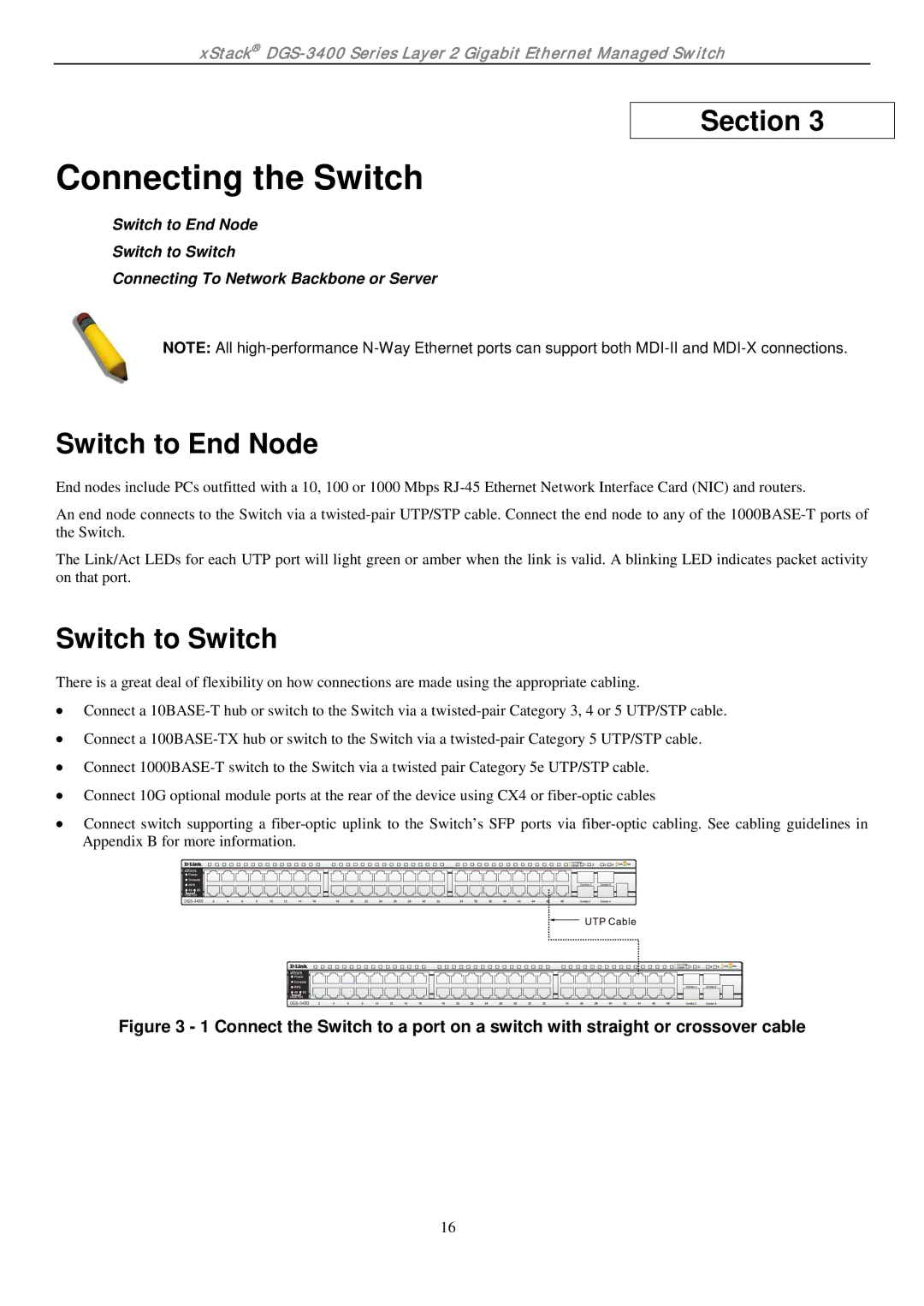
Figure 3 - 1 Connect the Switch to a port on a switch with straight or crossover cable

16

Page 25
Image 25
D-Link ethernet managed switch manual Connecting the Switch, Switch to End Node, Switch to Switch, Section