r t . d e l l . c o m
M e mo r y Ri se r Bo a r d C o mp o n en t s
w w w. d e l l . c o m s u p po
riser board A ![]()
![]()
![]()
![]()
![]()
![]()
![]()
![]()
![]()
![]()
![]()
![]() socket 4
socket 4 ![]()
![]()
![]()
![]()
![]()
![]()
![]()
![]()
![]()
![]()
![]() socket 3
socket 3
| socket 2 | |
socket 1 | ||
light | ||
| ||
riser board B | socket 4 | |
| ||
| socket 3 |
pair 4
pair 3
pair 2
pair 1
![]()
![]()
![]()
![]()
![]()
![]()
![]()
![]()
![]()
![]()
![]() socket 2
socket 2 ![]()
![]()
![]()
![]()
![]()
![]()
![]()
![]()
![]()
![]()
![]()
![]() socket 1
socket 1 ![]()
System Memory Installation Guidelines
Riser Board Installation
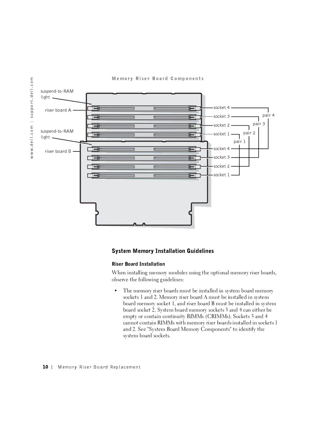
When installing memory modules using the optional memory riser boards, observe the following guidelines:
•The memory riser boards must be installed in system board memory sockets 1 and 2. Memory riser board A must be installed in system board memory socket 1, and riser board B must be installed in system board socket 2. System board memory sockets 3 and 4 can either be empty or contain continuity RIMMs (CRIMMs). Sockets 3 and 4 cannot contain RIMMs with memory riser boards installed in sockets 1 and 2. See "System Board Memory Components" to identify the system board sockets.
10
Memory Riser Board Replacement
