Stacking Dell PowerConnect 7000 Series Switches
required for reconfiguration. Additional stack members can immediately utilize existing configuration information such as routing and switching configurations, VLANs, ACLs, port profiles, and security certificates.
Stacking and Performance
For situations where there is a need to pass traffic between switches and the aggregate bandwidth required between PowerConnect 7000 Series switches does not exceed 64 Gbps (2 ports, 16 Gbps Tx and Rx each), a stacking configuration offers an attractive alternative to Link Aggregation Groups (LAGs). Stacking configuration is generally transparent to the operator and does not require configuration beyond cabling. In addition, failover times are generally faster in a stack configuration than in spanning tree or link aggregation group configurations. Note that other PowerConnect Series switches may have different supported bandwidths for stacking.
Stacking and Redundancy
By connecting a cable from the last switch in a stack back to the first switch, the operator ensures that a stack has the protection of redundant paths for control and data traffic, including support for LAGs configured across multiple switches. This means that any single point of failure (a switch or a stack cable failure) will not affect the overall operation of the remaining stack elements.
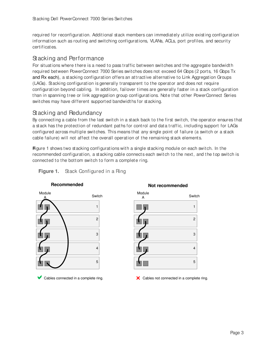
Figure# 1 shows two stacking configurations with a single stacking module on each switch. In the recommended configuration, a stacking cable connects each switch to the next, and the top switch is connected to the bottom switch to form a complete ring.
Figure 1. Stack Configured in a Ring
Recommended
Module | Switch | |
A | ||
| ||
| 1 | |
| 2 | |
| 3 | |
| 4 | |
| 5 |
aCables connected in a complete ring.
Not recommended
| Module | Switch | ||||
|
| A | ||||
|
|
|
| |||
|
|
|
|
|
|
|
|
|
|
|
| 1 |
|
|
|
|
|
|
| |
|
|
|
|
|
|
|
|
|
|
|
|
|
|
|
|
|
|
| 2 |
|
|
|
|
|
|
| |
|
|
|
|
|
|
|
|
|
|
|
|
|
|
|
|
|
|
|
|
|
|
|
|
|
| 3 |
|
|
|
|
|
|
| |
|
|
|
|
|
|
|
|
|
|
|
|
|
|
|
|
|
|
|
|
|
|
|
|
|
| 4 |
|
|
|
|
|
|
| |
|
|
|
|
|
|
|
|
|
|
|
|
|
|
|
|
|
|
|
|
|
|
|
|
|
| 5 |
|
|
|
|
|
|
| |
|
|
|
|
|
|
|
|
|
|
|
|
|
|
rCables not connected in a complete ring.
Page 3