Back to Contents Page
Processor Module
Dell™ Precision™ M4300 Service Manual
Removing the Processor Module
Installing the Processor Module
Removing the Processor Module
CAUTION: Before performing the following procedures, follow the safety instructions in the Product Information Guide.
NOTICE: To avoid electrostatic discharge, ground yourself by using a wrist grounding strap or by periodically touching a connector on the back panel of the computer.
NOTICE: Press and hold the processor down by applying slight pressure to the center of the processor while turning the cam screw to prevent intermittent contact between the cam screw and processor.
NOTICE: To avoid damage to the processor, hold the screwdriver so that it is perpendicular to the processor when turning the cam screw.
1.Follow the procedures in Before You Begin.
2.Remove the hinge cover (see Hinge Cover).
3.Remove the keyboard (see Keyboard).
4.Remove the display assembly (see Display Assembly).
5.Remove the palm rest (see Palm Rest).
6.Remove the processor
NOTICE: When removing the processor module, pull the module straight up. Be careful not to bend the pins on the processor module.
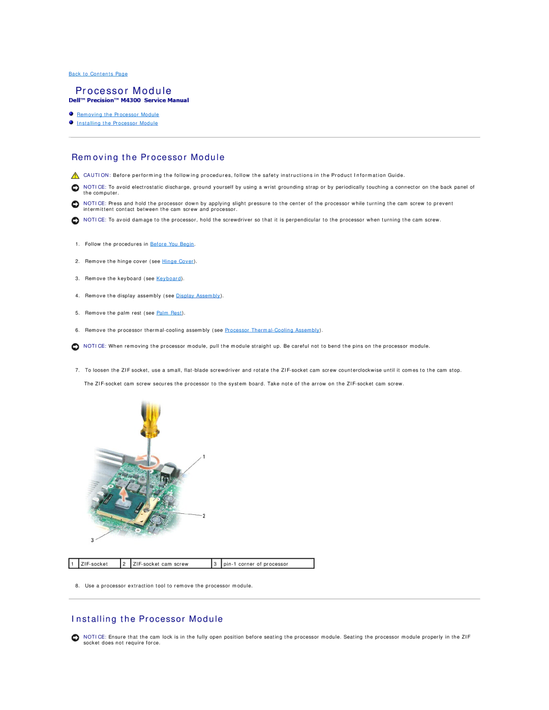
7.To loosen the ZIF socket, use a small,
The
1 | 2 | 3 | |||
|
|
|
|
|
|
8. Use a processor extraction tool to remove the processor module.
Installing the Processor Module
NOTICE: Ensure that the cam lock is in the fully open position before seating the processor module. Seating the processor module properly in the ZIF socket does not require force.