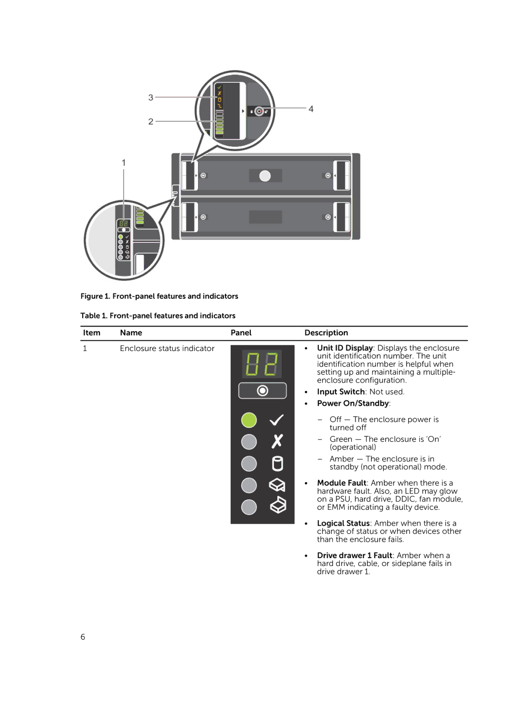
Figure 1. Front-panel features and indicators
Table 1.
Item | Name | Panel | Description |
|
|
|
|
1 | Enclosure status indicator |
| • Unit ID Display: Displays the enclosure |
|
|
| unit identification number. The unit |
|
|
| identification number is helpful when |
|
|
| setting up and maintaining a multiple‐ |
|
|
| enclosure configuration. |
|
|
| • Input Switch: Not used. |
|
|
| • Power On/Standby: |
|
|
| – Off — The enclosure power is |
|
|
| turned off |
|
|
| – Green — The enclosure is ‘On’ |
|
|
| (operational) |
|
|
| – Amber — The enclosure is in |
|
|
| standby (not operational) mode. |
|
|
| • Module Fault: Amber when there is a |
|
|
| hardware fault. Also, an LED may glow |
|
|
| on a PSU, hard drive, DDIC, fan module, |
|
|
| or EMM indicating a faulty device. |
|
|
| • Logical Status: Amber when there is a |
|
|
| change of status or when devices other |
|
|
| than the enclosure fails. |
|
|
| • Drive drawer 1 Fault: Amber when a |
|
|
| hard drive, cable, or sideplane fails in |
|
|
| drive drawer 1. |
6