In a full mesh, all eight ports joined together in the MLAG (four blue cables) are in the same port channel to achieve maximum redundancy.
To configure the
1.Enter the commands below for each corresponding switch in the topology.
2.Cable the configuration as shown.
3.Enable MLAG (using the feature vpc command) on each switch.
Similar commands are performed on all four MLAG peer switches. MLAG peers B and C are required to be consistent in their configurations following the guidelines set in Consistency of MLAG peers. MLAG peers D and E also follow the same requirements for consistency. Though MLAG partner switches A and F may have similar configurations in this particular scenario, they have no such consistency requirements to each other or to the peer switches.
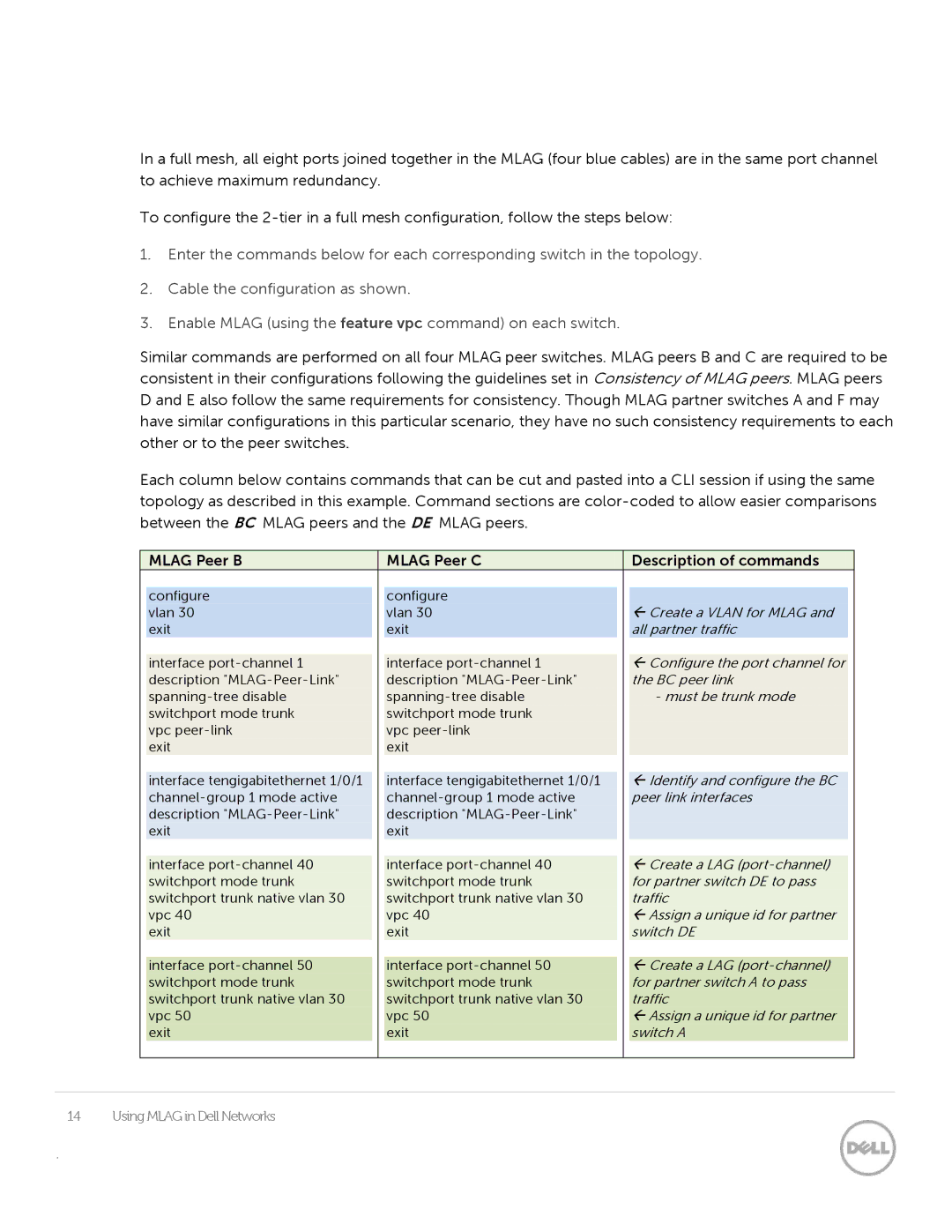
Each column below contains commands that can be cut and pasted into a CLI session if using the same topology as described in this example. Command sections are
|
| MLAG Peer B |
|
| MLAG Peer C |
|
| Description of commands |
|
|
|
|
|
|
|
|
|
|
|
|
|
|
| configure |
|
| configure |
|
|
|
|
|
|
| vlan 30 |
|
| vlan 30 |
|
| Create a VLAN for MLAG and |
|
|
|
| exit |
|
| exit |
|
| all partner traffic |
|
|
|
|
|
|
|
|
|
|
|
|
|
|
| interface |
|
| interface |
|
| Configure the port channel for |
|
|
|
| description |
|
| description |
|
| the BC peer link |
|
|
|
|
|
|
|
| - must be trunk mode |
|
| ||
|
| switchport mode trunk |
|
| switchport mode trunk |
|
|
|
|
|
|
| vpc |
|
| vpc |
|
|
|
|
|
|
| exit |
|
| exit |
|
|
|
|
|
|
|
|
|
|
|
|
|
|
|
|
|
| interface tengigabitethernet 1/0/1 |
|
| interface tengigabitethernet 1/0/1 |
|
| Identify and configure the BC |
|
|
|
|
|
|
|
| peer link interfaces |
|
| ||
|
| description |
|
| description |
|
|
|
|
|
|
| exit |
|
| exit |
|
|
|
|
|
|
|
|
|
|
|
|
|
|
|
|
|
| interface |
|
| interface |
|
| Create a LAG |
|
|
|
| switchport mode trunk |
|
| switchport mode trunk |
|
| for partner switch DE to pass |
|
|
|
| switchport trunk native vlan 30 |
|
| switchport trunk native vlan 30 |
|
| traffic |
|
|
|
| vpc 40 |
|
| vpc 40 |
|
| Assign a unique id for partner |
|
|
|
| exit |
|
| exit |
|
| switch DE |
|
|
|
|
|
|
|
|
|
|
|
|
|
|
| interface |
|
| interface |
|
| Create a LAG |
|
|
|
| switchport mode trunk |
|
| switchport mode trunk |
|
| for partner switch A to pass |
|
|
|
| switchport trunk native vlan 30 |
|
| switchport trunk native vlan 30 |
|
| traffic |
|
|
|
| vpc 50 |
|
| vpc 50 |
|
| Assign a unique id for partner |
|
|
|
| exit |
|
| exit |
|
| switch A |
|
|
|
|
|
|
|
|
|
|
|
|
|
|
|
|
|
|
|
|
|
|
|
|
14 Using MLAG in Dell Networks
.
