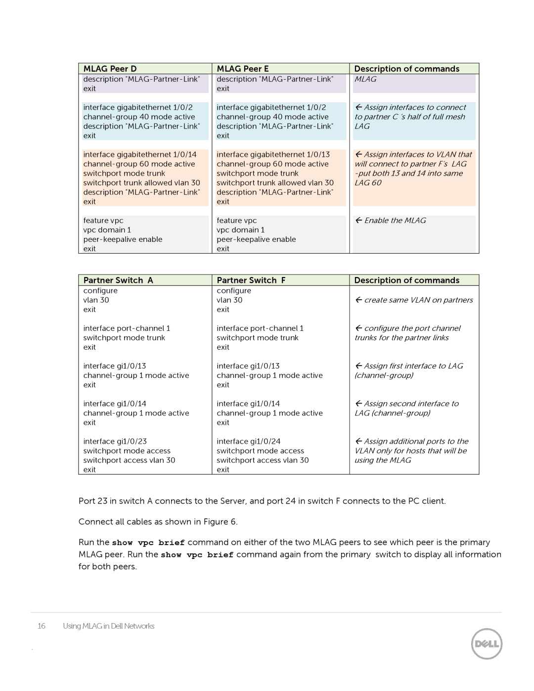
| MLAG Peer D |
|
| MLAG Peer E |
|
| Description of commands |
|
| description |
|
| description |
|
| MLAG |
|
| exit |
|
| exit |
|
|
|
|
|
|
|
|
|
|
|
|
|
| interface gigabitethernet 1/0/2 |
|
| interface gigabitethernet 1/0/2 |
|
| Assign interfaces to connect |
|
|
|
|
|
| to partner C ‘s half of full mesh |
| ||
| description |
|
| description |
|
| LAG |
|
| exit |
|
| exit |
|
|
|
|
|
|
|
|
|
|
|
|
|
| interface gigabitethernet 1/0/14 |
|
| interface gigabitethernet 1/0/13 |
|
| Assign interfaces to VLAN that |
|
|
|
|
|
| will connect to partner F’s LAG |
| ||
| switchport mode trunk |
|
| switchport mode trunk |
|
|
| |
| switchport trunk allowed vlan 30 |
|
| switchport trunk allowed vlan 30 |
|
| LAG 60 |
|
| description |
|
| description |
|
|
|
|
| exit |
|
| exit |
|
|
|
|
|
|
|
|
|
|
|
|
|
| feature vpc |
|
| feature vpc |
|
| Enable the MLAG |
|
| vpc domain 1 |
|
| vpc domain 1 |
|
|
|
|
|
|
|
|
|
|
| ||
| exit |
|
| exit |
|
|
|
|
Partner Switch A | Partner Switch F | Description of commands |
configure | configure |
|
vlan 30 | vlan 30 | create same VLAN on partners |
exit | exit |
|
interface | interface | configure the port channel |
switchport mode trunk | switchport mode trunk | trunks for the partner links |
exit | exit |
|
interface gi1/0/13 | interface gi1/0/13 | Assign first interface to LAG |
exit | exit |
|
interface gi1/0/14 | interface gi1/0/14 | Assign second interface to |
LAG | ||
exit | exit |
|
interface gi1/0/23 | interface gi1/0/24 | Assign additional ports to the |
switchport mode access | switchport mode access | VLAN only for hosts that will be |
switchport access vlan 30 | switchport access vlan 30 | using the MLAG |
exit | exit |
|
Port 23 in switch A connects to the Server, and port 24 in switch F connects to the PC client.
Connect all cables as shown in Figure 6.
Run the show vpc brief command on either of the two MLAG peers to see which peer is the primary MLAG peer. Run the show vpc brief command again from the primary switch to display all information for both peers.
16 Using MLAG in Dell Networks
.