1Introduction
MLAGs provide an
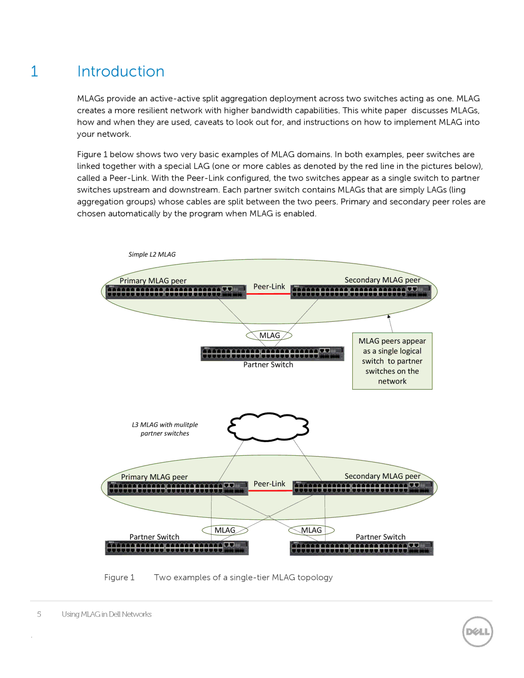
Figure 1 below shows two very basic examples of MLAG domains. In both examples, peer switches are linked together with a special LAG (one or more cables as denoted by the red line in the pictures below), called a Peer-Link. With the Peer-Link configured, the two switches appear as a single switch to partner switches upstream and downstream. Each partner switch contains MLAGs that are simply LAGs (ling aggregation groups) whose cables are split between the two peers. Primary and secondary peer roles are chosen automatically by the program when MLAG is enabled.
Simple L2 MLAG |
|
Primary MLAG peer | Secondary MLAG peer |
|
MLAG |
| |
MLAG peers appear | ||
| ||
| as a single logical | |
Partner Switch | switch to partner | |
switches on the | ||
| ||
| network | |
|
|
L3 MLAG with mulitple
partner switches
Primary MLAG peer | Secondary MLAG peer |
|
MLAG | MLAG |
Partner Switch | Partner Switch |
Figure 1 Two examples of a single-tier MLAG topology
5 | Using MLAG in Dell Networks |
.
