3Supported Topologies
MLAGs topologies contain several options. They can be a single layer (only one pair of MLAG peer switches) or two layers (two pair of MLAG peer switches).
Each MLAG domain can have anywhere from 1 to 8 partner switches. The
Topological parameter | Supported options |
|
|
# of peer switches per MLAG | 2 |
# of layers | 1 or 2 |
# of partner switches | 1 to 8 per MLAG |
# of | 1 to 8 active per MLAG (up to 8 more inactive) |
Table 2 Optional parameters for an MLAG topology
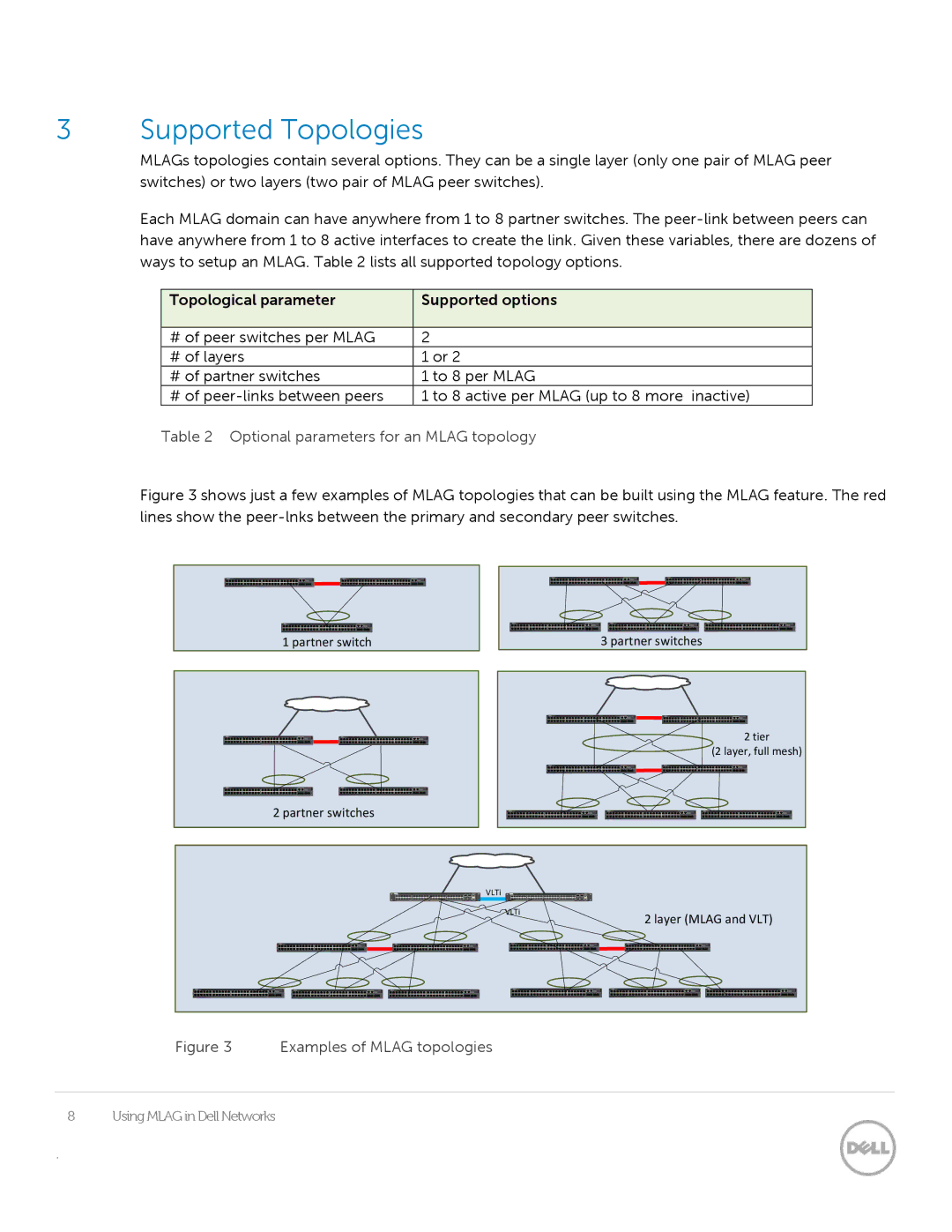
Figure 3 shows just a few examples of MLAG topologies that can be built using the MLAG feature. The red lines show the peer-lnks between the primary and secondary peer switches.
1 partner switch
3 partner switches
2 tier
(2 layer, full mesh)
2 partner switches
VLTi |
VLTi
Figure 3 Examples of MLAG topologies
8 | Using MLAG in Dell Networks |
.
2 layer (MLAG and VLT)
