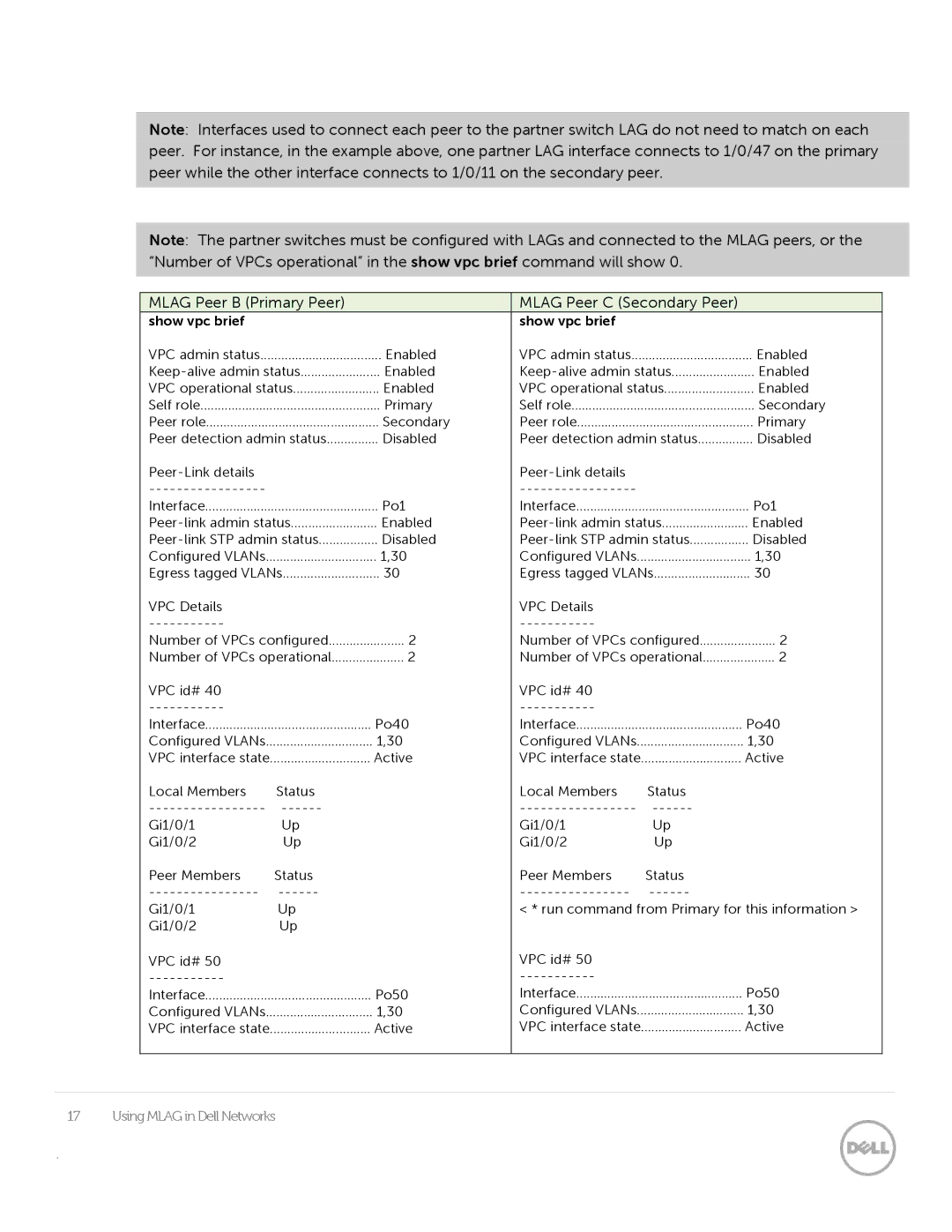
Note: Interfaces used to connect each peer to the partner switch LAG do not need to match on each peer. For instance, in the example above, one partner LAG interface connects to 1/0/47 on the primary peer while the other interface connects to 1/0/11 on the secondary peer.
Note: The partner switches must be configured with LAGs and connected to the MLAG peers, or the “Number of VPCs operational” in the show vpc brief command will show 0.
MLAG Peer B (Primary Peer) |
| MLAG Peer C (Secondary Peer) |
| ||
show vpc brief |
|
| show vpc brief |
|
|
VPC admin status | Enabled | VPC admin status | Enabled | ||
Enabled | Enabled | ||||
VPC operational status | Enabled | VPC operational status | Enabled | ||
Self role | Primary | Self role | Secondary | ||
Peer role | Secondary | Peer role | Primary | ||
Peer detection admin status | Disabled | Peer detection admin status | Disabled | ||
|
|
|
| ||
|
|
|
| ||
Interface | Po1 | Interface | Po1 | ||
Enabled | Enabled | ||||
Disabled | Disabled | ||||
Configured VLANs | 1,30 | Configured VLANs | 1,30 | ||
Egress tagged VLANs | 30 | Egress tagged VLANs | 30 | ||
VPC Details |
|
| VPC Details |
|
|
|
|
|
| ||
Number of VPCs configured | 2 | Number of VPCs configured | 2 | ||
Number of VPCs operational | 2 | Number of VPCs operational | 2 | ||
VPC id# 40 |
|
| VPC id# 40 |
|
|
|
|
|
| ||
Interface | Po40 | Interface | Po40 | ||
Configured VLANs | 1,30 | Configured VLANs | 1,30 | ||
VPC interface state | Active | VPC interface state | Active | ||
Local Members | Status |
| Local Members | Status |
|
|
| ||||
Gi1/0/1 | Up |
| Gi1/0/1 | Up |
|
Gi1/0/2 | Up |
| Gi1/0/2 | Up |
|
Peer Members | Status |
| Peer Members | Status |
|
|
| ||||
Gi1/0/1 | Up |
| < * run command from Primary for this information > | ||
Gi1/0/2 | Up |
|
|
|
|
VPC id# 50 |
|
| VPC id# 50 |
|
|
|
|
|
| ||
Interface | Po50 | Interface | Po50 | ||
Configured VLANs | 1,30 | Configured VLANs | 1,30 | ||
VPC interface state | Active | VPC interface state | Active | ||
|
|
|
|
|
|
17 Using MLAG in Dell Networks
.