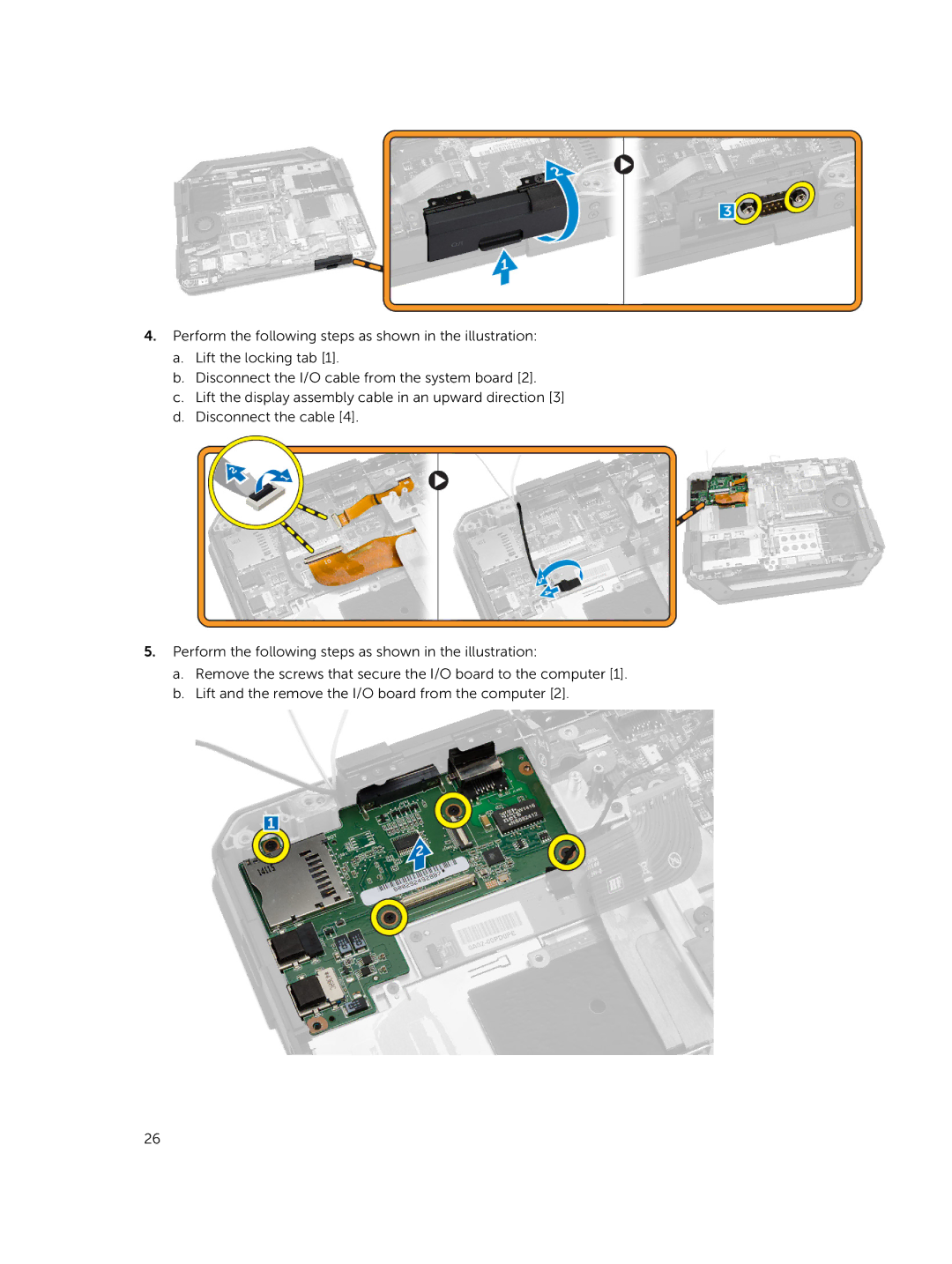
4.Perform the following steps as shown in the illustration:
a.Lift the locking tab [1].
b.Disconnect the I/O cable from the system board [2].
c.Lift the display assembly cable in an upward direction [3]
d.Disconnect the cable [4].
5.Perform the following steps as shown in the illustration:
a.Remove the screws that secure the I/O board to the computer [1].
b.Lift and the remove the I/O board from the computer [2].
26