7
8
9
10
11
12
13
14
15
Computer 5V/3.3V
GND
DDC data
DDC clock
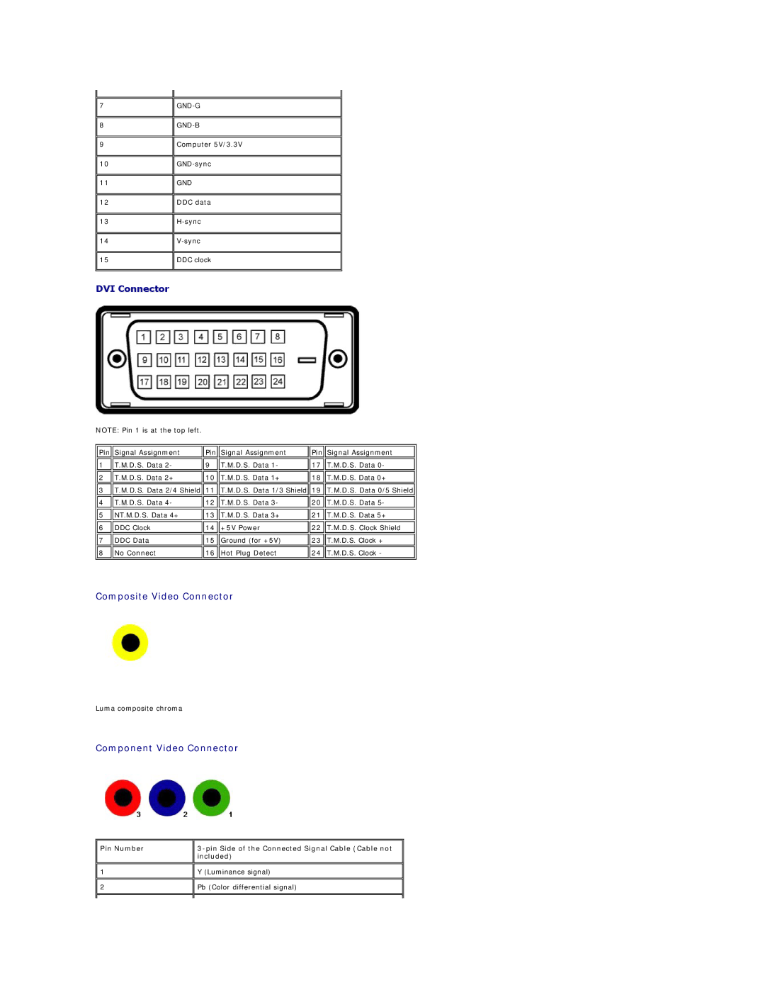
DVI Connector
NOTE: Pin 1 is at the top left.
Pin | Signal Assignment | Pin | Signal Assignment | Pin | Signal Assignment |
|
|
|
|
|
|
1 | T.M.D.S. Data 2- | 9 | T.M.D.S. Data 1- | 17 | T.M.D.S. Data 0- |
|
|
|
|
|
|
2 | T.M.D.S. Data 2+ | 10 | T.M.D.S. Data 1+ | 18 | T.M.D.S. Data 0+ |
|
|
|
|
|
|
3 | T.M.D.S. Data 2/4 Shield | 11 | T.M.D.S. Data 1/3 Shield | 19 | T.M.D.S. Data 0/5 Shield |
|
|
|
|
|
|
4 | T.M.D.S. Data 4- | 12 | T.M.D.S. Data 3- | 20 | T.M.D.S. Data 5- |
|
|
|
|
|
|
5 | NT.M.D.S. Data 4+ | 13 | T.M.D.S. Data 3+ | 21 | T.M.D.S. Data 5+ |
|
|
|
|
|
|
6 | DDC Clock | 14 | +5V Power | 22 | T.M.D.S. Clock Shield |
|
|
|
|
|
|
7 | DDC Data | 15 | Ground (for +5V) | 23 | T.M.D.S. Clock + |
|
|
|
|
|
|
8 | No Connect | 16 | Hot Plug Detect | 24 | T.M.D.S. Clock - |
|
|
|
|
|
|
Composite Video Connector
Luma composite chroma
Component Video Connector
Pin Number
1
2
![]()
![]() Y (Luminance signal)
Y (Luminance signal)
![]()
![]() Pb (Color differential signal)
Pb (Color differential signal)