3.To adjust, loosen the
C
D
Fig. 54
CROSS-CUT STOP
A block of wood placed at (B) Fig. 55 (clamped to the track arm with a small “C” clamp) will prevent unnecessary travel of the
![]()
![]() B
B
Fig. 55
ADJUSTING THE BLADE GUARD AND THE ANTI-KICKBACK ROD
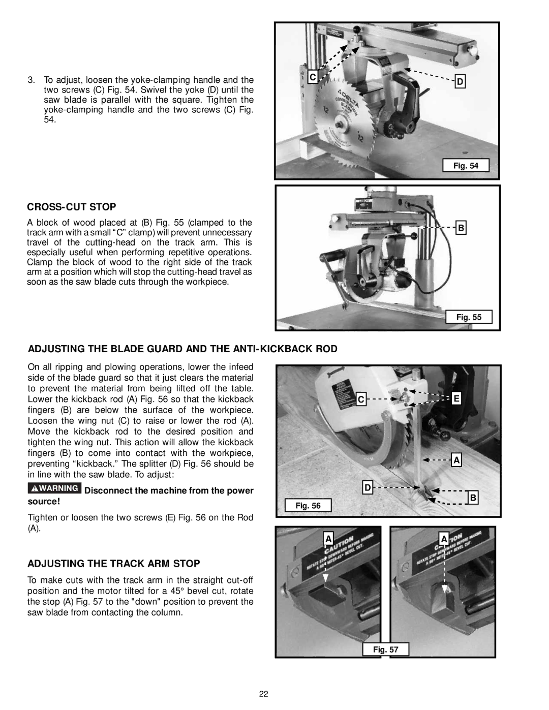
On all ripping and plowing operations, lower the infeed side of the blade guard so that it just clears the material to prevent the material from being lifted off the table. Lower the kickback rod (A) Fig. 56 so that the kickback fingers (B) are below the surface of the workpiece. Loosen the wing nut (C) to raise or lower the rod (A). Move the kickback rod to the desired position and tighten the wing nut. This action will allow the kickback fingers (B) to come into contact with the workpiece, preventing “kickback.” The splitter (D) Fig. 56 should be in line with the saw blade. To adjust:
![]() Disconnect the machine from the power source!
Disconnect the machine from the power source!
Tighten or loosen the two screws (E) Fig. 56 on the Rod
(A).
ADJUSTING THE TRACK ARM STOP
To make cuts with the track arm in the straight
C ![]()
![]()
![]() E
E
![]()
![]() A
A
D ![]()
![]()
B
Fig. 56
|
|
|
|
|
|
|
|
|
| A |
|
|
|
| A |
| |
|
|
|
|
|
|
|
|
|
|
|
|
|
|
|
|
|
|
Fig. 57
22
