![]() FOR YOUR OWN SAFETY, DO NOT CONNECT THE MACHINE TO THE POWER SOURCE UNTIL THE MACHINE IS COMPLETELY ASSEMBLED AND YOU READ AND UNDERSTAND THE ENTIRE INSTRUCTION MANUAL.
FOR YOUR OWN SAFETY, DO NOT CONNECT THE MACHINE TO THE POWER SOURCE UNTIL THE MACHINE IS COMPLETELY ASSEMBLED AND YOU READ AND UNDERSTAND THE ENTIRE INSTRUCTION MANUAL.
A
THIS MACHINE IS HEAVY. USE TWO
OR MORE PEOPLE WHEN LIFTING.
CASTERS |
| |
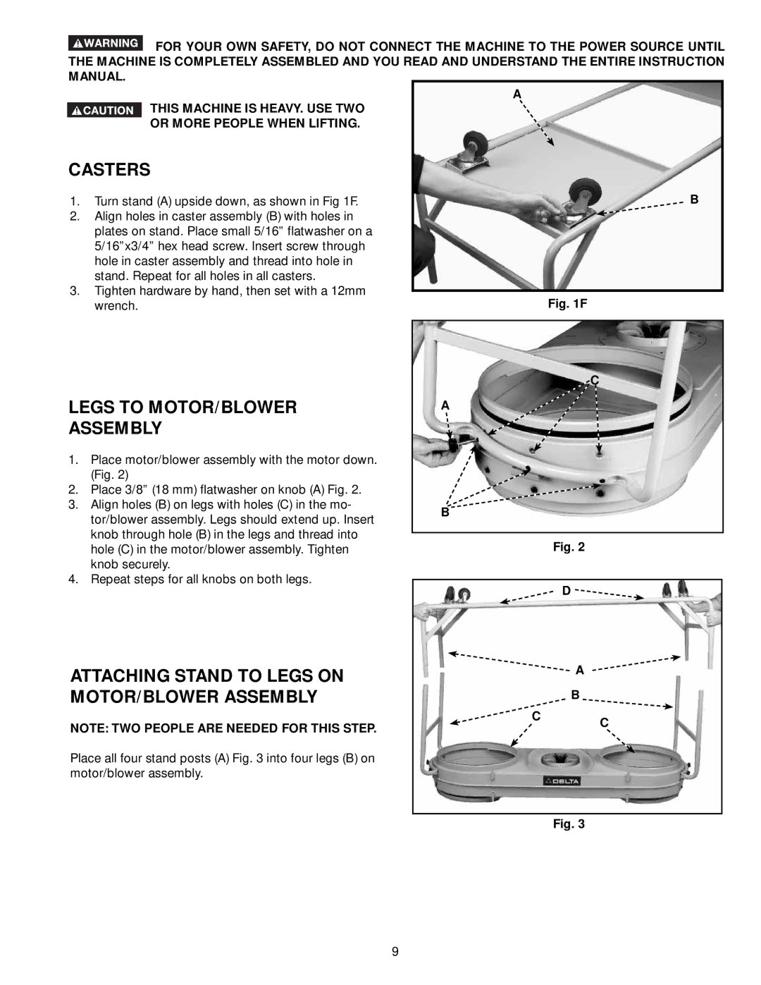
1. | Turn stand (A) upside down, as shown in Fig 1F. | B |
2. | Align holes in caster assembly (B) with holes in |
|
| plates on stand. Place small 5/16” flatwasher on a |
|
| 5/16”x3/4” hex head screw. Insert screw through |
|
| hole in caster assembly and thread into hole in |
|
| stand. Repeat for all holes in all casters. |
|
3.Tighten hardware by hand, then set with a 12mm
wrench. | Fig. 1F |
C
LEGS TO MOTOR/BLOWER | A | ||
ASSEMBLY |
|
| |
1. | Place motor/blower assembly with the motor down. |
|
|
| (Fig. 2) |
|
|
2. | Place 3/8” (18 mm) flatwasher on knob (A) Fig. 2. |
|
|
3. | Align holes (B) on legs with holes (C) in the mo- | B | |
| tor/blower assembly. Legs should extend up. Insert | ||
|
|
| |
| knob through hole (B) in the legs and thread into |
|
|
| Fig. 2 | ||
| hole (C) in the motor/blower assembly. Tighten | ||
| knob securely. |
|
|
4. | Repeat steps for all knobs on both legs. |
|
|
|
| ||
D ![]()
ATTACHING STAND TO LEGS ON |
| A |
|
| |
MOTOR/BLOWER ASSEMBLY |
| B |
NOTE: TWO PEOPLE ARE NEEDED FOR THIS STEP. | C | C |
| ||
|
|
Place all four stand posts (A) Fig. 3 into four legs (B) on motor/blower assembly.
Fig. 3
9
