assembly and adjustments
GROUNDINGBLADES | f_ _ I |
" | ./'_I / | NO | ADAPTER IS I _ | _ | ! | OVERLOAD I |
Jfl | I | AVAILABLEFORI | J | PROTECTORI | ||
" | II TH'sTYPELU°I |
|
| I | ||
| Figure 3 | J |
| Figure 4 | ||
|
|
|
|
|
| I |
MOTOR | SPECIFICATIONS | (Cont°d) |
| |||
| Hertz | (cycles) |
| 60 | ||
| Phase |
| Single | |||
| RPM | ........................... |
| 3450 | ||
| Rotation (viewed from left side |
| ||||
|
| when facing saw at operator |
| |||
|
| position |
| Clockwise | ||
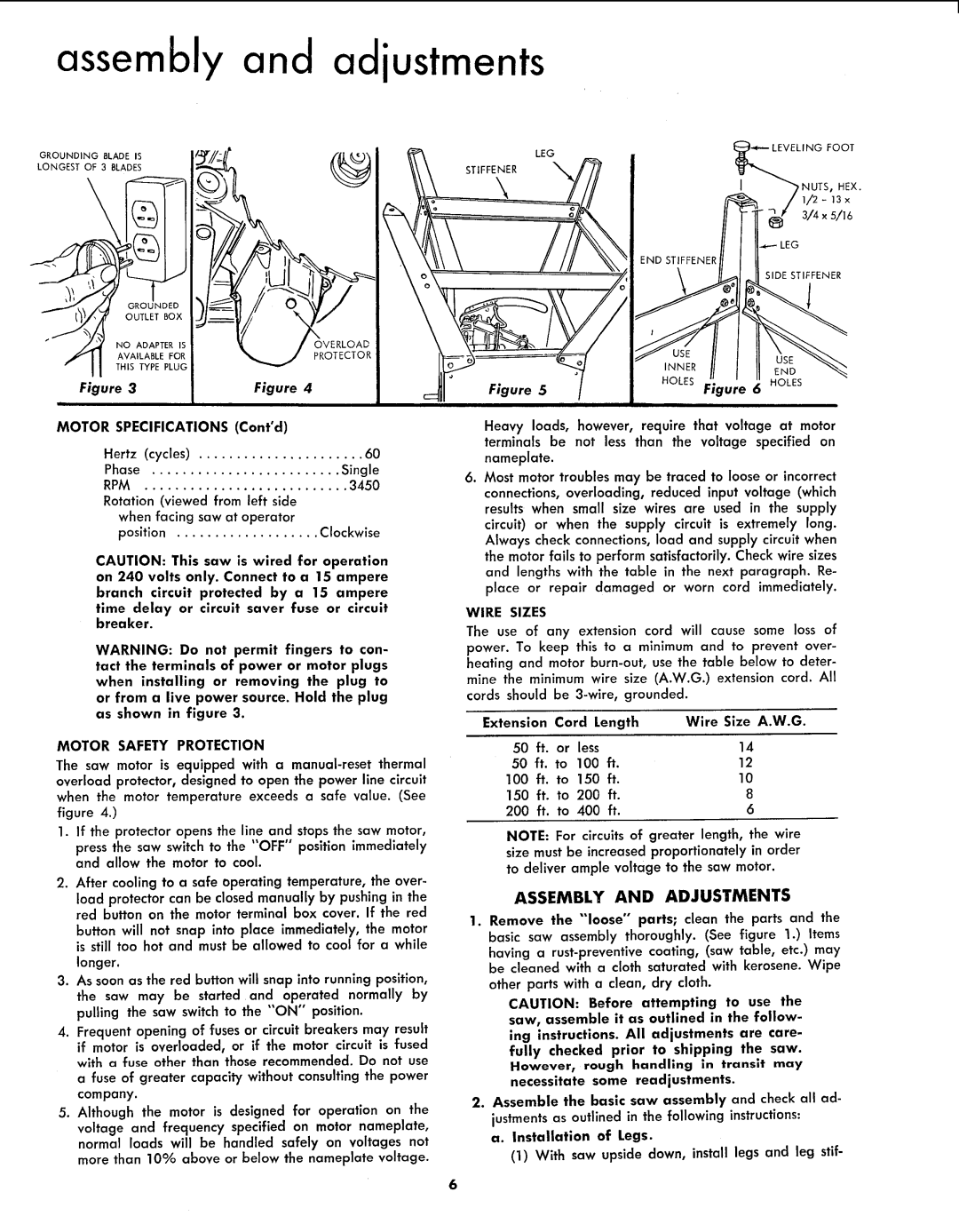
CAUTION: This saw is wired for operation on 240 volts only. Connect to a 15 ampere
branch circuit protected by a 15 ampere time delay or circuit saver fuse or circuit breaker.
WARNING: Do not permit fingers to con- tact the terminals of power or motor plugs when installing or removing the plug to or from a live power source. Hold the plug as shown in figure 3.
MOTOR SAFETY PROTECTION
The saw motor is equipped with a
overload protector, designed to open the power line circuit when the motor temperature exceeds a safe value. (See
figure 4.)
1.If the protector opens the line and stopsthe saw motor,
press the saw switch to the "OFF" position immediately and allow the motor to cool.
2.After cooling to a safe operating temperature, the over-
'EG
LING FOOT
NUTS, HEX.
/ iI
// I''_ _ 3/4x5/16
END STIFFENER
I SIDE STIFFENER
| INNER |
| |
| HOLES | 6 HOLES | |
Figure 5 | Figure | ||
|
Heavy loads, however, require that voltage at motor terminals be not less than the voltage specified on nameplate.
. Most motor troubles may be traced to loose or incorrect connections, overloading, reduced input voltage (which results when small size wires are used in the supply circuit) or when the supply circuit is extremely long. Always check connections, load and supply circuit when the motor fails to perform satisfactorily. Check wire sizes and lengths with the table in the next paragraph. Re- place or repair damaged or worn cord immediately.
WIRE SIZES
The use of any extension cord will cause some loss of power. To keep this to a minimum and to prevent over- heating and motor
Extension | Cord Length | Wire Size A.W.G. | |||
50 | ft. | or | less | 14 | |
50 | ft. | to | 100 | ft. | 12 |
100 | ft. | to | 150 | ft. | 10 |
150 | ft. | to | 200 | ft. | 8 |
200 | ft. | to 400 | ft. | 6 | |
NOTE: For circuits of greater length, the wire size must be increased proportionately in order to deliver ample voltage to the saw motor.
load protector can be closed manually by pushing in the red button on the motor terminal box cover. If the red
button will not snap into place immediately, the motor is still too hot and must be allowed to cool for a while
longer.
3.As soon as the red button will snap into running position, the saw may be started and operated normally by pulling the saw switch to the "'ON" position.
4.Frequent opening of fuses or circuit breakers may result if motor is overloaded, or if the motor circuit is fused with a fuse other than those recommended. Do not use
a fuse of greater capacity without consulting the power company.
5.Although the motor is designed for operation on the
voltage and frequency specified on motor nameplate, normal loads will be handled safely on voltages not more than 10% above or below the nameplate voltage.
ASSEMBLY AND ADJUSTMENTS
1.Remove the "'loose" parts; clean the parts and the basic saw assembly thoroughly. (See figure 1.) Items having a
other parts with a clean, dry cloth.
CAUTION: Before attempting to use the saw, assemble it as outlined in the follow-
ing instructions. All adjustments are care- fully checked prior to shipping the saw. However_ rough handling in transit may necessitate some readjustments.
2.Assemble the basic saw assembly and check all ad- justments as outlined in the following instructions:
a. Installation of Legs.
(1)With saw upside down, install legs and leg stif-
6