assembly and adjustments
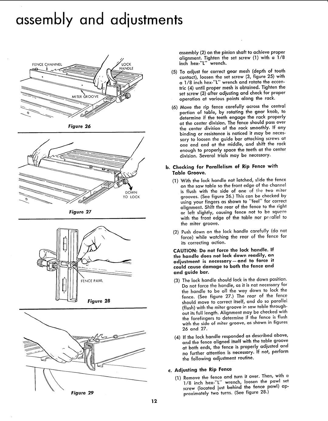
Figure 26
DOWN
TO LOCK
Figure 27
FENCE PAWL
Figure 28
Figure 29
assembly (2) on the pinion shaft to achieve proper alignment. Tighten the set screw (1) with a 1/8 inch
(5)To adjust for correct gear mesh (depth of tooth contact), loosen the set screw (3, figure 25) with a 1/8 inch
(6)Move the rip fence carefully across the central portion of table, by rotating the gear knob, to determine if the teeth engage the rack properly at the center division. The fence should pass over the center division of the rack smoothly. If any binding or resistance is noticed it may be neces- sary to loosen the guide bar attaching screws at one end and at the middle, and shift the rack enough to properly space the teeth at the center division. Several trials may be necessary.
b.Checking for Parallelism of Rip Fence with Table Groove.
(1)With the lock handle not latched, slide the fence on the saw table so the front edge of the channel is flush with the side of one of the two miter grooves. (See figure 26.) This can be checked by using your fingers as shown to "feel" for correct alignment. Shift the rear of the fence to the right or left slightly, causing fence not to be squcre with the front edge of the table nor pr_allel to the miter groove.
(2)Push down on the lock handle carefully (do not force) while watching the rear of the fence for its correcting action.
CAUTION: Do not force the lack handle. If
the handle does not lock down readily, an
adjustment is
and guide bar.
(3)The lock handle should lock in the down position. Do not force the handle, as it is not necessary for the handle to be all the way down to lock the fence. (See figure 27.) The rear of the fence should move to correct itself, and do so parallel (flush) with the miter groove in saw table through- out its full length. Alignment may be checked with the forefingers to determine if the fence is flush with the side of miter groove, as shown in figures 26 and 27.
(4)If the lock handle responded as described above, and the fence aligned itself with the table groove at both ends, the fence is properly adjusted and no further attention is necessary. If not, perform the following adjustment routine.
€. Adjusting the Rip Fence
(1)Remove the fence and turn it over. Then, with a 1/8 inch
screw (located just behind the fence pawl) ap- proximately two turns. (See figure 28.)
12