Figure
(2) Using a 5/32 inch
set screw at the rear of the fence approximately two turns. (See figure 29.) This screw is located in the fence lock just inside the channel as shown.
(3)Place the fence back on saw table and notice that the lock handle offers no resistance at any position.
(4)Push the lock handle down in "locked" position and, using a 1/8 inch
(5)Raise the lock handle, push the fence to one side (off square) at the rear. Then lock the fence with the lock handle, while watching to make sure it
"'corrects" itself. Repeat this operation two or more times. The fence should "'correct'" itself each time it is locked.
(6)Raise the lock handle and align the fence with the miter groove (at the front end of the groove) as shown in figure 26. Push the lock handle down.
(7)Check for correct alignment with saw table groove for the full length of the fence. If it is aligned at the front but out of alignment at the rear, loosen the two
(8)Check for "automatic correcting" by releasing the lock lever, shifting the fence off square at the rear, then locking it. The fence should square
itself automatically and be flush (parallel) with
the miter groove each time the handle is locked down.
(9)Lock the fence with the lock handle, using a 5/32 inch
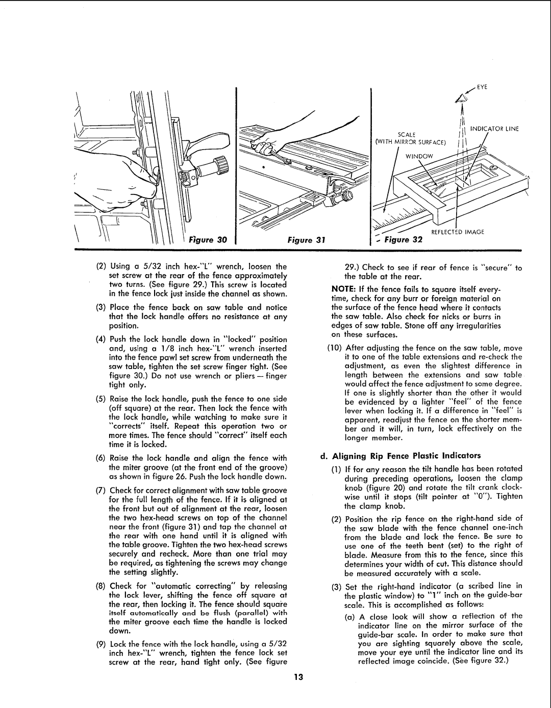
SCALE
(WITH MIRROR SURFACE)
WINDOW
REFLECTED IMAGE
31 | .. Figure 32 |
29.) Check to see if rear of fence is "secure" to the table at the rear.
NOTE: If the fence fails to square itself every-
time, check for any burr or foreign material on the surface of the fence head where it contacts
the saw table. Also check for nicks or burrs in
edges of saw table. Stone off any irregularities on these surfaces.
(10)After adjusting the fence on the saw table, move it to one of the table extensions and
adjustment, as even the slightest difference in length between the extensions and saw table would affect the fence adjustment to some degree. If one is slightly shorter than the other it would be evidenced by a lighter "feel" of the fence lever when locking it. If a difference in "feel" is apparent, readjust the fence on the shorter mem- ber and it will, in turn, lock effectively on the longer member.
d.Aligning Rip Fence Plastic Indicators
(1)If for any reason the tilt handle has been rotated during preceding operations, loosen the clamp knob (figure 20) and rotate the tilt crank clock- wise until it stops (tilt pointer at "0"). Tighten the clamp knob.
(2)Position the rip fence on the
determines your width of cut. This distance should be measured accurately with a scale.
(3)Set the
the plastic window) to "1" inch on the
(a)A close look will show a reflection of the indicator line on the mirror surface of the
13