maintenance
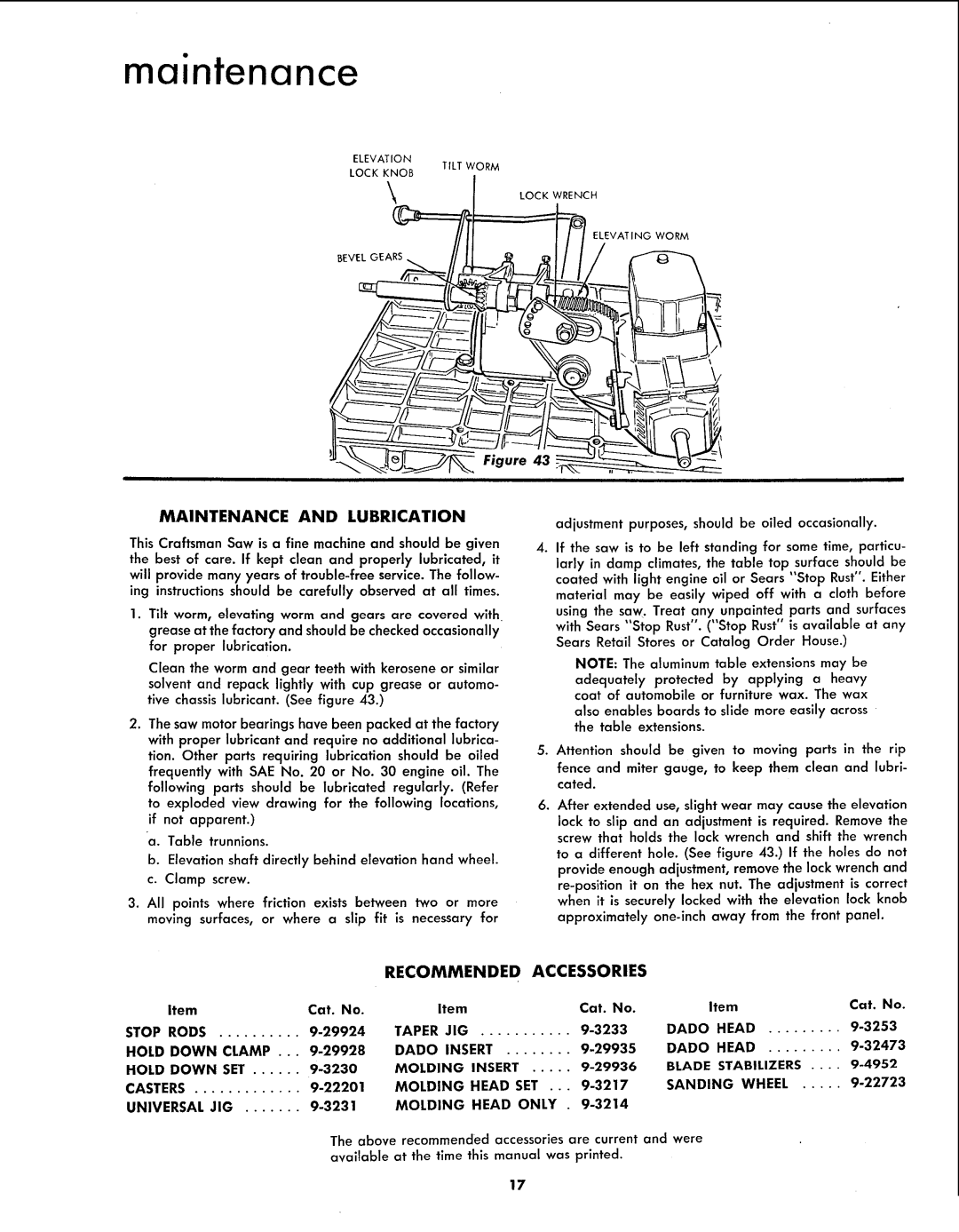
ELEVATION
LOCK KNOB
TILT WORM
LOCK WRENCH
BEVEL GEARS__ | _ | ELEVATING WORM |
MAINTENANCE AND LUBRICATION
This Craftsman Saw is a fine machine and should be given the best of care. If kept clean and properly lubricated, it will provide many years of
1.Tilt worm, elevating worm and gears are covered with. grease at the factory and should be checked occasionally for proper lubrication.
Clean the worm and gear teeth with kerosene or similar solvent and repack lightly with cup grease or automo- tive chassis lubricant. (See figure 43.)
2.The saw motor bearings have been packed at the factory with proper lubricant and require no additional lubrica- tion. Other parts requiring lubrication should be oiled frequently with SAE No. 20 or No. 30 engine oil. The following parts should be lubricated regularly. (Refer to exploded view drawing for the following locations, if not apparent.)
a.Table trunnions.
b.Elevation shaft directly behind elevation hand wheel. c. Clamp screw.
3.All points where friction exists between two or more moving surfaces, or where a slip fit is necessary for
i
adjustment purposes, should be oiled occasionally.
4.If the saw is to be left standing for some time, particu-
larly in damp climates, the table top surface should be coated with light engine oil or Sears "Stop Rust". Either
material may be easily wiped off with a cloth before using the saw. Treat any unpainted parts and surfaces
with Sears "Stop Rust". ("Stop Rust" is available at any Sears Retail Stores or Catalog Order House.)
NOTE: The aluminum table extensions may be
adequately protected by applying a heavy coat of automobile or furniture wax. The wax
also enables boards to slide more easily across the table extensions.
5.Attention should be given to moving parts in the rip
fence and miter gauge, to keep them clean and lubri- cated.
6.After extended use, slight wear may cause the elevation
lock to slip and an adjustment is required. Remove the screw that holds the lock wrench and shift the wrench
to a different hole. (See figure 43.) If the holes do not provide enough adjustment, remove the lock wrench and
RECOMMENDED ACCESSORIES
Item |
| Cat. No. | Item |
|
|
| Cat. No. |
STOP RODS | .......... | TAPER JIG | ........... |
| |||
HOLD DOWN | CLAMP ... | DADO INSERT |
| ........ | |||
HOLD DOWN | SET | MOLDING | INSERT | ||||
CASTERS | MOLDING | HEAD | SET ... | ||||
UNIVERSAL JIG | MOLDING | HEAD | ONLY | . | |||
|
| The above recommended | accessories are current | ||||
|
| available | at the time | this | manual was printed. | ||
Item | Cat. No. | |
DADO | HEAD | |
DADO | HEAD | |
BLADE | STABILIZERS .... | |
SANDING WHEEL | ||
and were
17