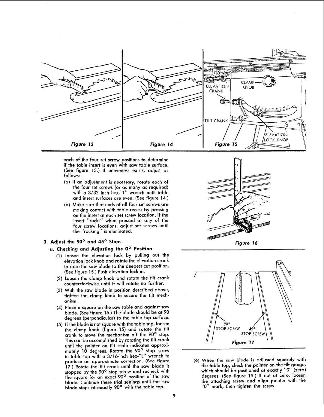
Figure 13 | Figure 14 |
each of the four set screw positions to determine if the table insert is even with saw table surface.
(See figure 13.) If uneveness exists, adjust as follows:
(a)If an adjustment is necessary, rotate each of the four set screws (or as many as required) with a 3/32 inch
(b)Make sure that ends of all four set screws are making contact with table recess by pressing on the insert at each set screw location. If the insert "rocks" when pressed at any of the four screw locations, adjust set screws until the "'rocking" is eliminated.
3.Adjust the 90 ° and 45 ° Stops.
a. Checking and Adjusting the 0 ° Position
(1)Loosen the elevation lock by pulling out the elevation lock knob and rotate the elevation crank
to raise the saw blade to the deepest cut position. (See figure 15.) Push elevation lock in.
(2)Loosen the clamp knob and rotate the tilt crank counterclockwise until it will rotate no farther.
(3)With the saw blade in position described above,
tighten the clamp knob to secure the tilt mech- anism.
(4)Place a square on the saw table and against saw blade. (See figure 16.) The blade should be at 90
degrees (perpendicular) to the table top surface.
(5)If the blade is not square with the table top, loosen
the clamp knob (figure 15) and rotate the tilt crank to move the mechanism off the 90 ° stop. This can be accomplished by rotating the tilt crank until the pointer on tilt scale indicates approxi- mately 10 degrees. Rotate the 90 ° stop screw in table top with a
FLEVATIOI_KNOB
CRANK
TILT CRANK-
.OCK KNOB
Figure 15
Figure 16
/
STOPSCREW 45°
STOPSCRE_
Figure 17
(6)When the saw blade is adjusted squarely with the table top, check the pointer on the tilt gauge, which should be positioned at exactly "0" (zero) degrees. (See figure 15.) If not at zero, loosen the attaching screw and align pointer with the "0" mark, then tighten the screw.