assembly and adiustments
SIDE VIEW
4 3 2 1
4 /
SAW TABLESPACER GUIDE BAR
RACK
| SCREW |
|
| /4 - 20 x | 21N._ |
LOCKW_ | SWITCH | BOX |
|
Figure 11
(2)Attach this assembly to the center hole in the table and secure the assembly with a 1/4 inch Iockwasher and
tighten the nut until all attaching screws are in position.
(3)Place each rack in position (as shown in figure
11)and insert a
guide bar, spacer and table extension. Secure with a 1/4 inch Iockwasher and
nut. (See figure 10.)
(4)Place switch box in position (either to right hand or left hand side of saw table as desired). Attach with two
(5)Complete attachment of opposlte rack with two more screws, aligned with table in the same
sequence described above. Tighten all screws securely.
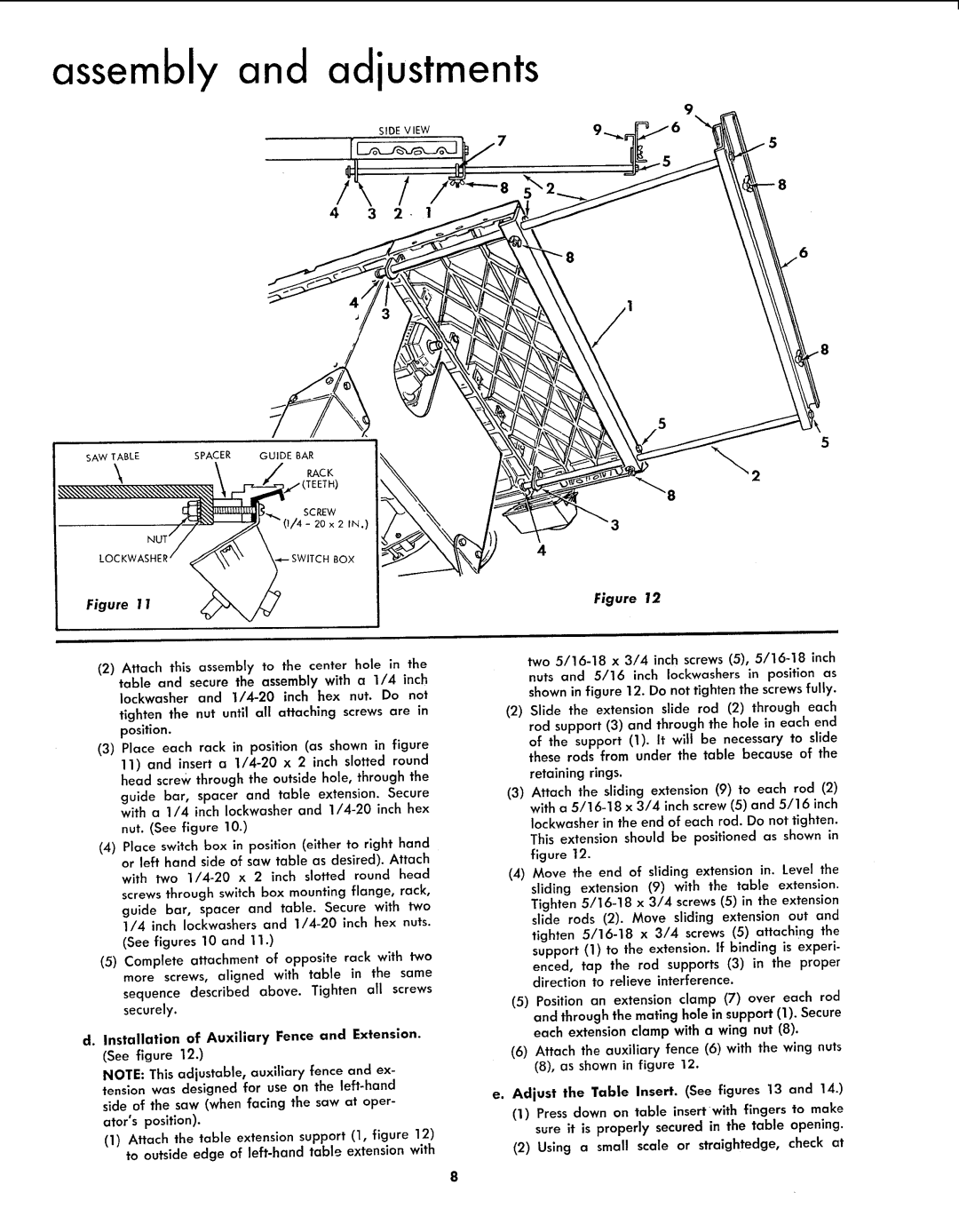
d.Installation of Auxiliary Fence and Extension. (See figure 12.)
NOTE: This adjustable, auxiliary fence and ex- tension was designed for use on the
(1)Attach the table extension support (1, figure 12) to outside edge of
5
4
Figure 12
two
(2)Slide the extension slide rod (2) through each rod support (3) and through the hole in each end
of the support (I). It will be necessary to slide these rods from under the table because of the
retaining rings.
(3)Attach the sliding extension (9) to each rod (2) with a
Iockwasher in the end of each rod. Do not tighten. This extension should be positioned as shown in figure 12.
(4)Move the end of sliding extension in. Level the sliding extension (9) with the table extension. Tighten
(5)Position an extension clamp (7) over each rod and through the mating hole in support (1). Secure each extension clamp with a wing nut (8).
(6)Attach the auxiliary fence (6) with the wing nuts (8), as shown in figure 12.
e.Adjust the Table Insert. (See figures 13 and 14.)
(1)Press down on table insertwith fingers to make sure it is properly secured in the table opening.