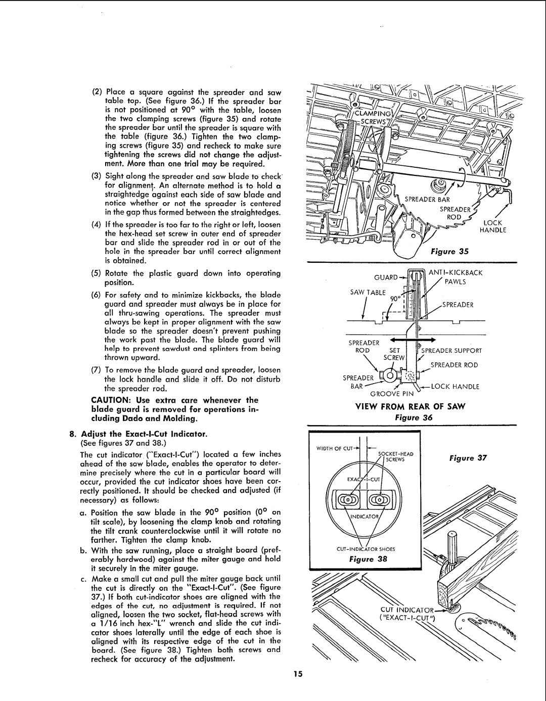
(2)Place a square against the spreader and saw table top. (See figure 36.) If the spreader bar is not positioned at 90 ° with the table, loosen the two clamping screws (figure 35) and rotate the spreader bar until the spreader is square with the table (figure 36.) Tighten the two clamp- ing screws (figure 35) and recheck to make sure tightening the screws did not change the adjust- ment. More than one trial may be required.
(3)Sight along the spreader and saw blade to check'
for alignmenl;. An alternate method is to hold a straightedge against each side of saw blade and notice whether or not the spreader is centered in the gap thus formed between the straightedges.
(4)If the spreader is too far to the right or left, loosen the
(5)Rotate the plastic guard down into operating position.
(6)For safety and to minimize kickbacks, the blade guard and spreader must always be in place for all
always be kept in proper alignment with the saw blade so the spreader doesn't prevent pushing the work past the blade. The blade guard will help to prevent sawdust and splinters from being thrown upward.
(7)To remove the blade guard and spreader, loosen the lock handle and slide it off. Do not disturb
the spreader rod.
CAUTION: Use extra care whenever the blade guard is removed far operations in- cluding Dado and Molding.
8.Adjust the
The cut indicator
mine precisely where the cut in a particular board will occur, provided the cut indicator shoes have been cor-
rectly positioned. It should be checked and adjusted (if necessary) as follows:
a.Position the saw blade in the 90 ° position (0 ° on
tilt scale), by loosening the clamp knob and rotating the tilt crank counterclockwise until it will rotate no
farther. Tighten the clamp knob.
b.With the saw running, place a straight board (pref- erably hardwood) against the miter gauge and hold it securely in the miter gauge.
c.Make a small cut and pull the miter gauge back until
the cut is directly on the
GUARD "_ _,,_ ';AK.wCLKsBAC
SAWTABLE9oo 111"
SPREADER : lib :
ROD SETI _SPREADERSUPPORT
\SCREWl I/
LI SPREA°ERR°D
SPREADER
K.ANOLE
GROOVE PIN -
VIEW FROM REAR OF SAW
Figure 36
WIDTH OF
|
| Figure 37 | ||
_/I | SCREWS | |||
| ||||
EXA( |
|
|
Figure 38
15