assembly and adjustments
ARBOR WRENCH
\
SHAFTq
ELEVATIONPOINTER
WRENCH
CRANK
CLAMP KNOB
aASE OF | TILT |
COMBINATION SQUARI
ELEVATION
Figure 18 | Figure | Figure 20 | LOCK | KNOB |
|
|
| //! | / |
| sc,_ | REAR |
|
|
|
| OF SAW | MARK | SCALE |
| PENCIL |
| ||
| PENCIL |
| ||
|
|
|
REAR OF SAW
MARK |
|
Figure 21 | Figure 22 |
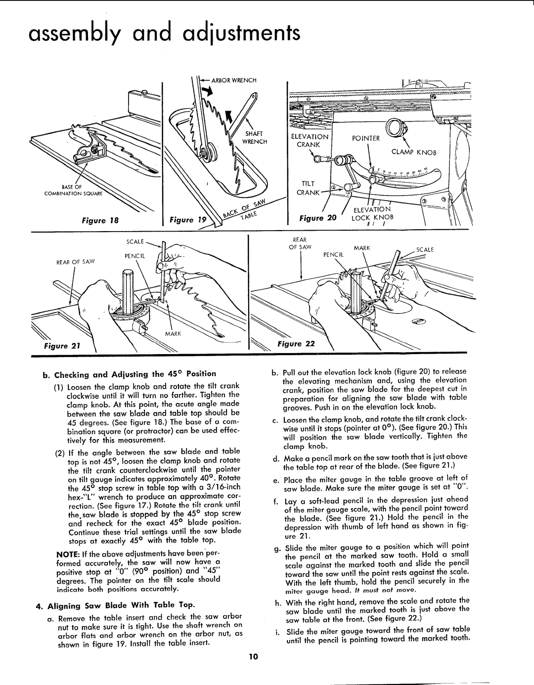
b. Checking and Adjusting the 45 ° Position | b. Pull out the elevation lock knob (figure 20) to release |
(1)Loosen the clamp knob and rotate the tilt crank clockwise until it will turn no farther. Tighten the clamp knob. At this point, the acute angle made between the saw blade and table top should be 45 degrees. (See figure 18.) The base of a com- bination square (or protractor) can be used effec- tively for this measurement.
(2)If the angle between the saw blade and table top is not 45 °, loosen the clamp knob and rotate the tilt crank counterclockwise until the pointer on tilt gauge indicates approximately 40 ° . Rotate the 45 ° stop screw in table top with a
NOTE: If the above adjustments have been 'per- formed accurately, the saw will now have a positive stop at "'0" (90 ° position) and "45" degrees. The pointer on the tilt scale should indicate both positions accurately.
4.Aligning Saw Blade With Table Top.
a. Remove the table insert and check the saw arbor
nut to make sure it is tight. Use the shaft wrench on arbor flats and arbor wrench on the arbor nut, as
shown in figure 19. Install the table insert.
the elevating mechanism and, using the elevation crank, position the saw blade for the deepest cut in preparation for aligning the saw blade with table grooves. Push in on the elevation lock knob.
c.Loosenthe clamp knob, and rotate the tilt crank clock- wise until it stops(pointer at 0°). (See figure 20.) This will position the saw blade vertically. Tighten the clamp knob.
d.Make a pencil mark on the saw tooth that is just above the table top at rear of the blade. (See figure 21.)
e.Place the miter gauge in the table groove at left of saw blade. Make sure the miter gauge is set at "0".
f.Lay a
g.Slide the miter gauge to a position which will point the pencil at the marked saw tooth. Hold a small scale against the marked tooth and slide the pencil
toward the saw until the point rests against the scale. With the left thumb, hold the pencil securely in the
miter gauge head. It must not move.
h. With the right hand, remove the scale and rotate the saw blade until the marked tooth is just above the saw table at the front. (See figure 22.)
i.Slide the miter gauge toward the front of saw table until the pencil is pointing toward the marked tooth.
10