Insert the scale between the pencil point and blade, as shown in figure 22. If the saw is parallel to the table groove, the scale will just "slide" into the gap between the pencil point and blade. If the scale will not enter this gap, or is loose in the check shown in figure 22, an adjustment of the table trunnlons is required. Proceed as follows:
(1)Tighten the clamp knob firmly (figure 20) and loosen the two screws which secure each table
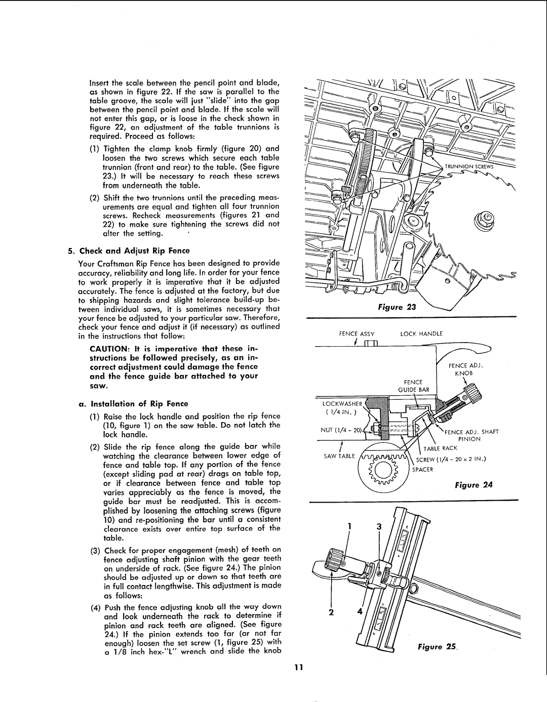
trunnion (front and rear) to the table. (See figure 23.) It will be necessary to reach these screws from underneath the table.
(2)Shift the two trunnlons until the preceding meas- urements are equal and tighten all four trunnion screws. Recheck measurements (figures 21 and
22)to make sure tightening the screws did not alter the setting.
5. Check and Adjust Rip Fence
Your Craftsman Rip Fence has been designed to provide accuracy, reliability and long life. In order for your fence to work properly it is imperative that it be adjusted accurately. The fence is adjusted at the factory, but due to shipping hazards and slight tolerance
check your fence and adjust it (if necessary) as outlined in the instructions that follow:
CAUTION: It is imperative that these in- structions be followed precisely, as an in- correct adjustment could damage the fence and the fence guide bar attached to your
saw.
a.Installation of Rip Fence
(1)Raise the lock handle and position the rip fence (10, figure 1) on the saw table. Do not latch the lock handle.
(2)Slide the rip fence along the guide bar while watching the clearance between lower edge of
fence and table top. If any portion of the fence (except sliding pad at rear) drags on table top, or if clearance between fence and table top varies appreciably as the fence is moved, the guide bar must be readjusted. This is accom- plished by loosening the attaching screws (figure
10)and
(3)Check for proper engagement (mesh) of teeth on fence adjusting shaft pinion with the gear teeth on underside of rack. (See figure 24.) The pinion
should be adjusted up or down so that teeth are in full contact lengthwise. This adjustment is made as follows:
(4)Push the fence adjusting knob all the way down and look underneath the rack to determine if
pinion and rack teeth are aligned. (See figure 24.) If the pinion extends too far (or not far enough) loosen the set screw (1, figure 25) with a 1/8 inch
@
Figure 23
FENCE ASSY | LOCK HANDLE |
inn
FENCE ADJ.
KNOB
FENCE_
GUIDE BAR _
NUT | (],4 - | 20).__ | _N, | F ENCpE NAt_N SHAF T |
SAW | TABLE | _ | SCREW (1/4 | - 20 x 2 IN.) |
|
|
| SPACER |
|
Figure 24
2
11