assembly and adjustments
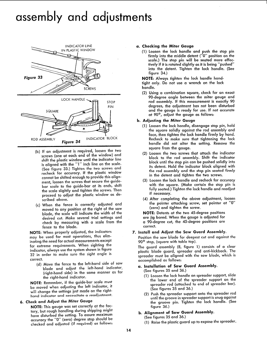
INDICATOR LINE IN PLASTIC WINDOW
a. Checking the Miter Gauge
(1)Loosen the lock handle and push the stop pin firmly into the middle detent ("0'"position on the scale.) The stop pin will be seated more effec- tively if it is rotated slightly as it is being "'pushed'"
Figure 33
SCREWS
into the detent. Tighten the lock handle. (See figure 34.)
NOTE: Always tighten the lock handle hand- tight only. Do not use a wrench on the lock handle.
(2)Using a combination square, check for an exact
LOCK HANDLE
STOP
PIN
SQUARE
ROD ASSEMBLY | INDICATOR | BLocK |
|
|
Figure 34
(b)If an adjustment is required, loosen the two screws (one at each end of the window) and
shift the plastic window until the indicator line is aligned with the "'1" inch line on the scale. (See figure 33.) Tighten the two screws and recheck for accuracy. If the plastic window cannot be shifted enough to provide this align- merit, loosen the screws that secure the guide- bar scale to the
proceed to adjust the plastic window as de- scribed above.
(c)When the fence is correctly adjusted and moved to any position at the right of the saw blade, the scale will indicate the width of the desired cut. Make several trial settings and
check by measuring with a scale from the fence to the blade.
NOTE: When properly adjusted, the indicators may be used for most operations, thus elim- inating the need for actual measurements except for extreme requirements. When sighting the indicator, always use the system shown in figure 32 in order to make sure the sight angle is correct.
(d)Move the fence to the
NOTE: Remember, if the
6. Check and Adjust the Miter Gauge
NOTE: This gauge was set correctly at the fac- tory, but rough handling during shipping might have disturbed the setting. To assure maximum
accuracy the "0 °°(zero) degree stop should be checked and adjusted (if required) as follows:
b. Adjusting the Miter Gauge
(1)Loosen the lock handle, disengage stop pin, hold
the square solidly against the rod assembly and face, then tighten the lock handle firmly by hand.
Recheck to make sure that tightening the lock handle did not alter the setting. Remove the square from the gauge.
(2)Loosen the two screws that attach the indicator block to the rod assembly. Shift the indicator block until the stop pin can be pushed solidly into its detent. Hold the indicator block aligned with
the rod assembly and the stop pin seated firmly in the detent and tighten the two screws.
(3)Loosen the lock handle and recheck for accuracy with the square. (Make certain the stop pin is fully seated.) Tighten the lock handle and readjust if necessary.
(4)After completing the above adjustment, loosen the pointer attaching screw, set pointer at "0" (zero) and tighten the screw.
NOTE: Detents at the two
7.Install and Adjust the Saw Guard Assembly. Position the saw blade for deepest cut and against the 90 ° stop, (square with table top).
The guard assembly (8, figure 1) consists of a clear plastic blade guard, spreader and
a.Installatlan af Saw Guard Assembly. (See figures 35 and 36.)
(1)Loosenthe lock handle on spreader support, slide the lower end of the spreader support on the
spreader rod (attached to end of spreader bar). (See figures 35 and 36.)
(2)Push the spreader support onto the spreader rod until the groove in spreader support is snug against the groove pin. Tighten the lock handle. (See figure 36.)
b.Alignment af Saw Guard Assembly. (See figures 35 and 36.)
(1)Raisethe plastic guard up to expose the spreader.
14