MACRO-CPU Hardware Reference
3U MACRO-CPU JUMPER AND SWITCH CONFIGURATIONS
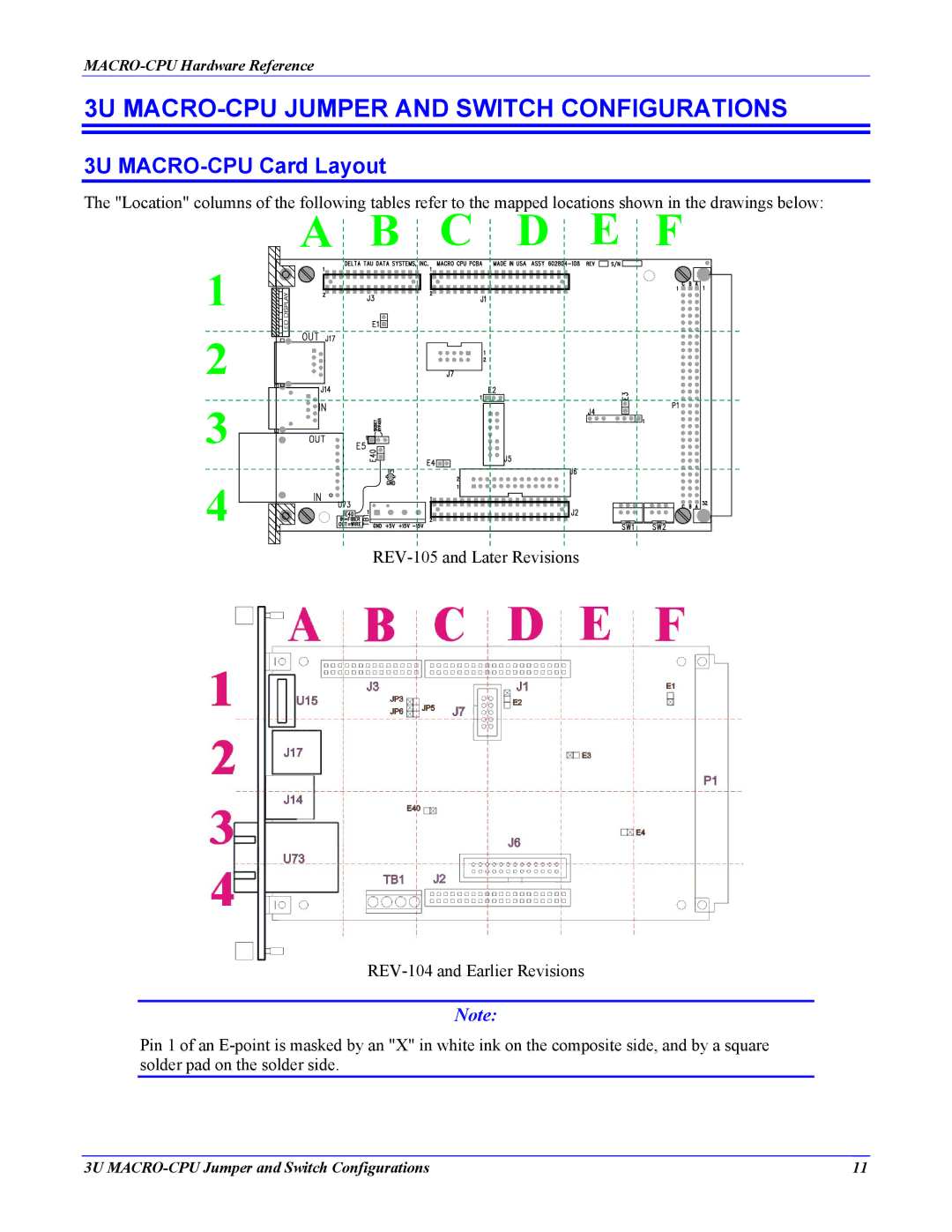
3U MACRO-CPU Card Layout
The "Location" columns of the following tables refer to the mapped locations shown in the drawings below:
A  B
B  C
C  D
D  E
E  F
F
1 |
2 |
3 |
4 |
Note:
Pin 1 of an
3U | 11 |