MACRO-CPU Hardware Reference
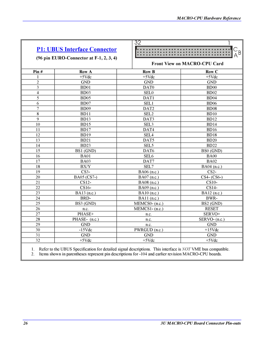
P1: UBUS Interface Connector
(96 pin
Front View on
Pin # | Row A | Row B | Row C |
1 | +5Vdc | +5Vdc | +5Vdc |
2 | GND | GND | GND |
3 | BD01 | DAT0 | BD00 |
4 | BD03 | SEL0 | BD02 |
5 | BD05 | DAT1 | BD04 |
6 | BD07 | SEL1 | BD06 |
7 | BD09 | DAT2 | BD08 |
8 | BD11 | SEL2 | BD10 |
9 | BD13 | DAT3 | BD12 |
10 | BD15 | SEL3 | BD14 |
11 | BD17 | DAT4 | BD16 |
12 | BD19 | SEL4 | BD18 |
13 | BD21 | DAT5 | BD20 |
14 | BD23 | SEL5 | BD22 |
15 | BS1 (GND) | DAT6 | BS0 (GND) |
16 | BA01 | SEL6 | BA00 |
17 | BA03 | DAT7 | BA02 |
18 | BX/Y | SEL7 | BA04 (n.c.) |
19 | CS3- | BA06 (n.c.) | CS2- |
20 | BA05 | BA07 (n.c.) | CS4- |
21 | CS12- | BA08 (n.c.) | CS10- |
22 | CS16- | BA09 (n.c.) | CS14- |
23 | BA13 (n.c.) | BA10 (n.c.) | BA12 (n.c.) |
24 | BRD- | BA11 (n.c.) | BWR- |
25 | BS3 (GND) | MEMCS0- (n.c.) | BS2 (GND) |
26 | n.c. | MEMCS1- (n.c.) | RESET |
27 | PHASE+ | n.c. | SERVO+ |
28 | PHASE- (n.c.) | n.c. | SERVO- (n.c.) |
29 | GND | n.c. | GND |
30 | PWRGUD (n.c.) | +15Vdc | |
31 | GND | GND | GND |
32 | +5Vdc | +5Vdc | +5Vdc |
1. Refer to the UBUS Specification for detailed signal descriptions. This interface is NOT VME bus compatible.
2. Items shown in parentheses represent pin descriptions for
26 | 3U |