ENGLISH
Speaker system connections
•Connect the speaker terminals with the speakers making sure that like polarities are matched (< with <, > with >). Mismatching of polarities will result in weak central sound, unclear orientation of the various instruments, and the sense of direction of the stereo being impaired.
•When making connections, take care that none of the individual conductors of the speaker cord come in contact with adjacent terminals, with other speaker cord conductors, or with the rear panel.
NOTE:
NEVER touch the speaker terminals when the power is on. Doing so could result in electric shocks.
Speaker Impedance
•When speaker systems A and B are use separately, speakers with an impedance of 4 to 16 Ω /ohms can be connected for use as speakers.
•Be careful when using two pairs of speakers (A + B) at the same time, since use of speakers with an impedance of 8 to 16 Ω /ohms.
•The protector circuit may be activated if the set is played for long periods of time at high volumes when speakers with an impedance lower than the specified impedance are connected.
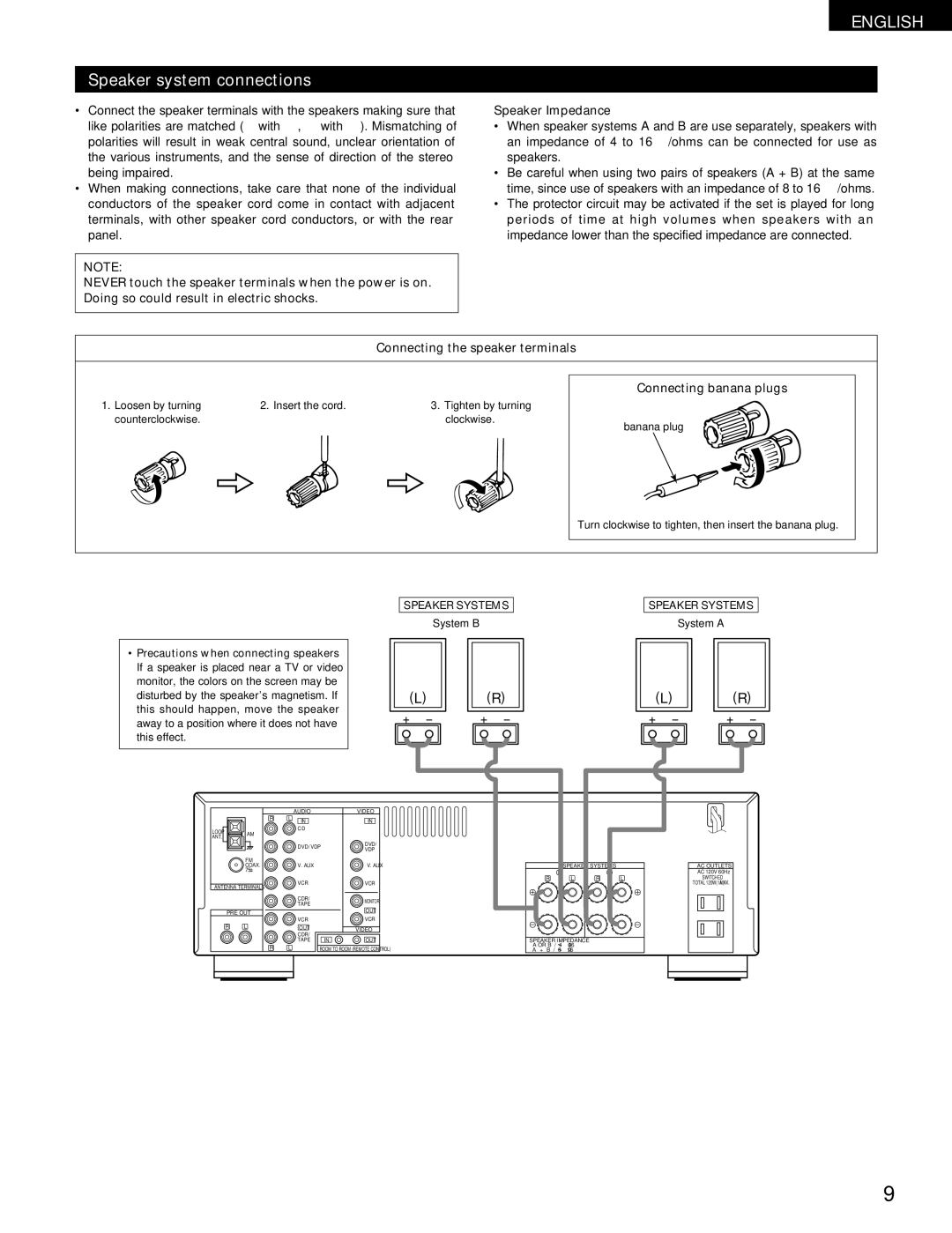
Connecting the speaker terminals
1. Loosen by turning | 2. Insert the cord. | 3. Tighten by turning |
counterclockwise. |
| clockwise. |
Connecting banana plugs
banana plug
Turn clockwise to tighten, then insert the banana plug.
•Precautions when connecting speakers If a speaker is placed near a TV or video monitor, the colors on the screen may be disturbed by the speaker’s magnetism. If this should happen, move the speaker away to a position where it does not have this effect.
SPEAKER SYSTEMS
System B
|
|
|
|
|
|
|
|
|
|
|
| (L) |
|
|
| (R) |
| ||||
|
|
|
|
|
|
|
|
|
|
|
|
|
|
|
|
|
|
|
|
|
|
|
|
|
|
|
|
|
|
|
|
|
|
|
|
|
|
|
|
|
|
|
|
|
|
|
|
|
|
|
|
|
|
|
SPEAKER SYSTEMS
System A
|
|
|
|
|
|
|
|
|
|
|
| (L) |
|
|
| (R) |
| ||||
|
|
|
|
|
|
|
|
|
|
|
|
|
|
|
|
|
|
|
|
|
|
|
|
|
|
|
|
|
|
|
|
|
|
|
|
|
|
|
|
|
|
|
|
|
|
|
|
|
|
|
|
|
|
|
|
|
| AUDIO |
| VIDEO |
| R | L | IN |
| IN |
|
|
|
| ||
LOOP | AM |
| CD |
|
|
|
|
|
| ||
ANT. |
|
|
|
| |
|
|
|
|
| |
|
|
| DVD/ VDP |
| DVD/ |
|
|
|
| VDP | |
|
|
|
|
| |
| FM |
|
|
|
|
| COAX. |
| V. AUX |
| V. AUX |
| 75 |
|
|
|
|
ANTENNA TERMINALS |
| VCR |
| VCR | |
|
|
|
| ||
|
|
| CDR/ |
| MONITOR |
|
|
| TAPE |
| |
|
|
|
|
| |
PRE OUT |
|
|
| OUT | |
| VCR |
| VCR | ||
|
|
|
| ||
R | L |
| OUT |
| VIDEO |
|
|
| CDR/ |
| |
|
|
| IN | OUT | |
|
|
| TAPE | ||
| R | L |
| ROOM TO ROOM (REMOTE CONTROL) | |
SPEAKER SYSTEMS
B |
|
| A |
R | L | R | L |
SPEAKER IMPEDANCE |
|
| |
A OR B / 4 | 16 |
|
|
A + B / 8 | 16 |
|
|
AC OUTLETS
AC 120V 60Hz
SWITCHED
TOTAL 120W(1A.) MAX.
9