INSTALLING TO WALL
Continued
12
Marking Screw Locations
1.Tape mounting bracket to wall where heater will be located. Make sure mount- ing bracket is level.
WARNING
WARNING ICON | G 001 |
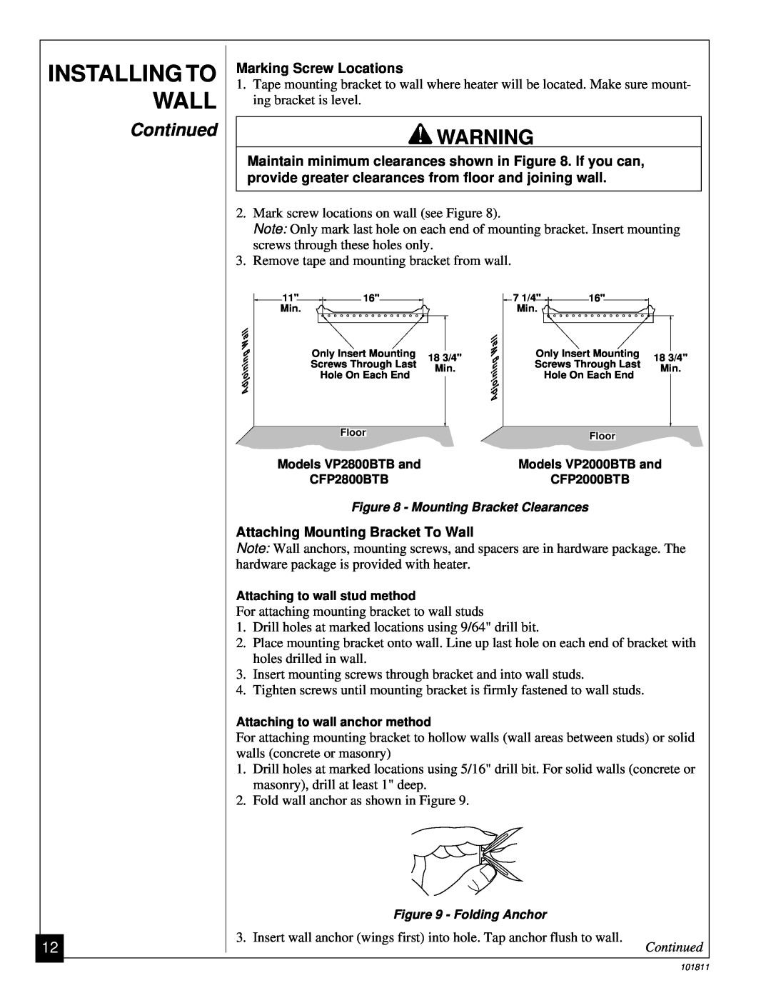
Maintain minimum clearances shown in Figure 8. If you can, provide greater clearances from floor and joining wall.
2.Mark screw locations on wall (see Figure 8).
Note: Only mark last hole on each end of mounting bracket. Insert mounting screws through these holes only.
3.Remove tape and mounting bracket from wall.
11" | 16" | 7 1/4" | 16" |
Min. |
| Min. |
|
AdjoiningWall |
| AdjoiningWall | Only Insert Mounting |
| ||
Only Insert Mounting | 18 3/4" |
| 18 3/4" | |||
Screws Through Last | Min. |
| Screws Through Last | Min. | ||
Hole On Each End |
| Hole On Each End | ||||
|
|
| ||||
Floor |
|
|
| Floor |
|
|
|
|
|
|
|
| |
Models VP2800BTB and |
|
| Models VP2000BTB and | |||
CFP2800BTB |
|
| CFP2000BTB |
| ||
Figure 8 - Mounting Bracket Clearances
Attaching Mounting Bracket To Wall
Note: Wall anchors, mounting screws, and spacers are in hardware package. The hardware package is provided with heater.
Attaching to wall stud method
For attaching mounting bracket to wall studs
1.Drill holes at marked locations using 9/64" drill bit.
2.Place mounting bracket onto wall. Line up last hole on each end of bracket with holes drilled in wall.
3.Insert mounting screws through bracket and into wall studs.
4.Tighten screws until mounting bracket is firmly fastened to wall studs.
Attaching to wall anchor method
For attaching mounting bracket to hollow walls (wall areas between studs) or solid walls (concrete or masonry)
1.Drill holes at marked locations using 5/16" drill bit. For solid walls (concrete or masonry), drill at least 1" deep.
2.Fold wall anchor as shown in Figure 9.
Figure 9 - Folding Anchor
3. Insert wall anchor (wings first) into hole. Tap anchor flush to wall.
Continued
101811