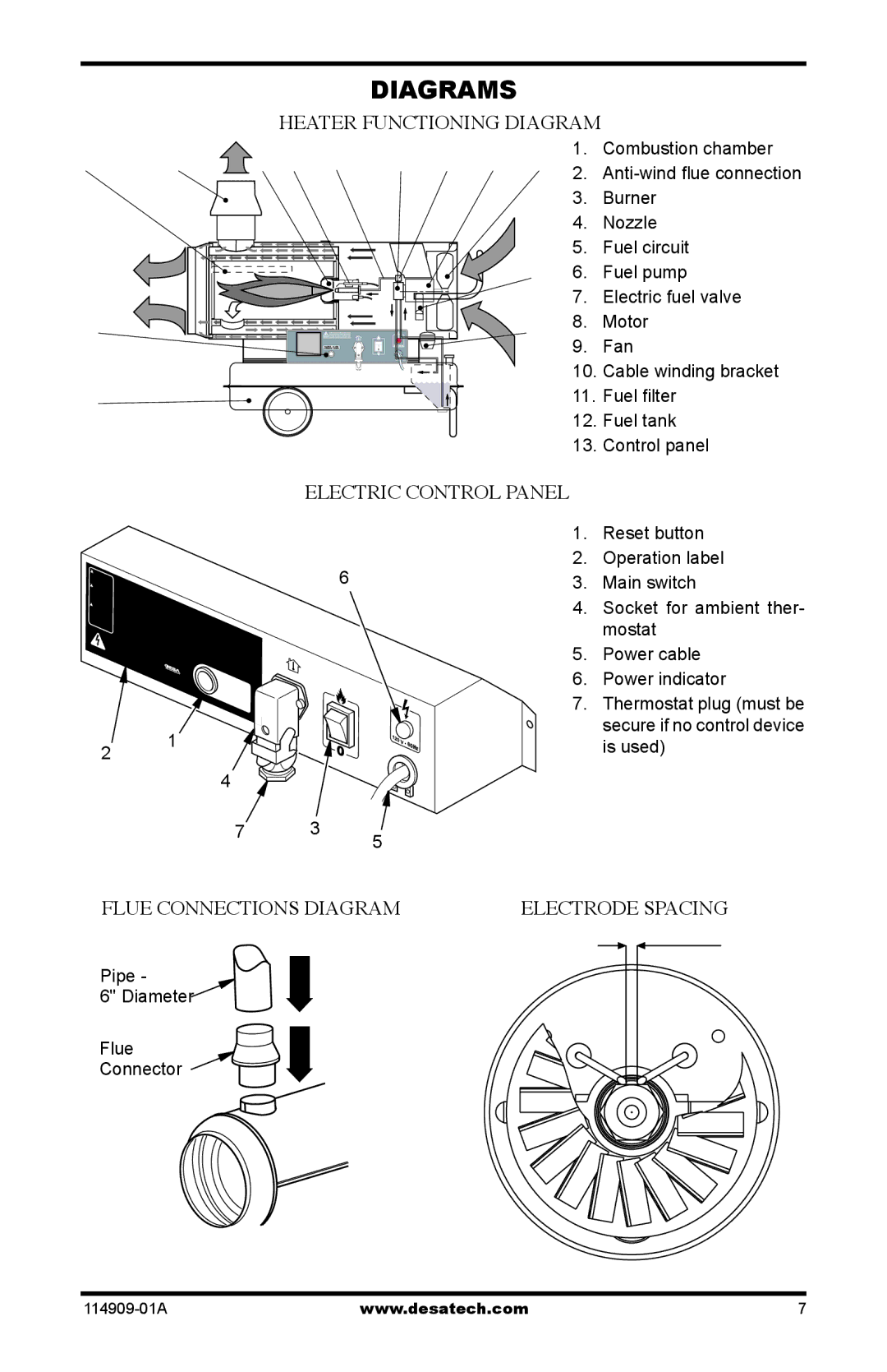
160-IF, 280-IF specifications
Desa 280-IF and Desa 160-IF are innovative and advanced models in the world of water heaters. These devices are designed to provide efficient heating solutions for residential and commercial needs, ensuring dependable performance and energy savings. Both models are equipped with a range of cutting-edge technologies and features that set them apart from traditional water heating systems.One of the standout features of the Desa 280-IF is its high-efficiency rating, which significantly reduces energy consumption while providing optimal water heating. This model is engineered with advanced insulation materials that minimize heat loss, thereby ensuring that the water remains heated for longer periods. The Desa 160-IF is similarly designed, focusing on efficiency and performance while catering to smaller applications or homes with lower hot water demand.
In terms of technology, both models utilize a robust and user-friendly digital control system. This system allows users to easily set, monitor, and adjust the water temperature, ensuring maximum comfort. The intuitive interface is designed for simplicity, making it accessible for all users, regardless of their technical expertise.
Safety is a prime consideration in the design of Desa 280-IF and Desa 160-IF. Both models are equipped with multiple safety features, including over-temperature protection, automatic shut-off mechanisms, and pressure relief valves, ensuring safe operation even in challenging conditions. Furthermore, their compact designs make them suitable for various installation environments, including tight spaces in urban settings.
Durability is another hallmark trait of these models. Constructed from high-quality materials, the Desa 280-IF and Desa 160-IF are built to withstand the rigors of daily use. Their resistance to corrosion and wear prolongs the lifespan of the units, making them a wise investment for consumers.
Additional features include remote monitoring capabilities for enhanced convenience, allowing users to manage their water heating needs from their smartphones or other devices.
As a whole, Desa 280-IF and Desa 160-IF embody the integration of efficiency, innovation, safety, and durability, making them top choices for modern water heating solutions. Whether for a bustling household or a quieter residence, these models provide the comfort and reliability that consumers expect in today's fast-paced world.

