Refer to the following table for clearance between roof and termination.
ROOF PITCH | MINIMUM HEIGHT ABOVE ROOF | |
| ft | mm |
FLAT - 7/12 | 1 | 305 |
7/12 - 8/12 | 1.5 | 457 |
8/12 - 9/12 | 2 | 610 |
9/12 - 10/12 | 2.5 | 762 |
10/12 - 11/12 | 4 | 1219 |
12/12 - 14/12 | 5 | 1524 |
14/12 - 16/12 | 6 | 1829 |
16/12 - 18/12 | 7 | 2134 |
18/12 - 20/12 | 7.5 | 2286 |
20/12 - 21/12 | 8 | 2438 |
FRAMING
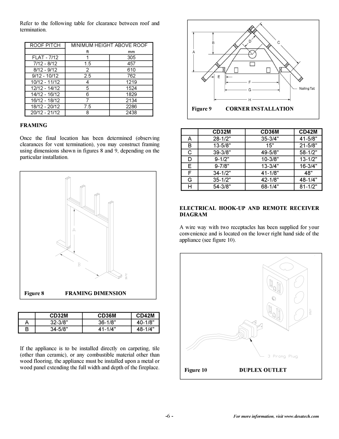
Once the final location has been determined (observing clearances for vent termination), you may construct framing using dimensions shown in figures 8 and 9, depending on the particular installation.
|
|
|
|
|
|
|
|
|
|
|
|
|
|
|
|
|
|
|
| Figure 8 | FRAMING DIMENSION |
|
|
| ||
|
|
|
|
|
|
|
|
|
|
|
|
|
|
|
|
| |
|
|
|
| CD32M | CD36M | CD42M |
| |
|
| A |
|
|
|
|
| |
|
| B |
|
|
|
|
| |
If the appliance is to be installed directly on carpeting, tile (other than ceramic), or any combustible material other than wood flooring, the appliance must be installed upon a metal or wood panel extending the full width and depth of the fireplace.
| Figure 9 | CORNER INSTALLATION |
|
| ||
|
|
|
|
|
|
|
|
|
|
|
|
|
|
|
|
| CD32M | CD36M | CD42M |
|
| A |
|
| |||
| B |
| 15" |
| ||
| C |
|
| |||
| D |
|
| |||
| E |
|
| |||
| F |
| 48" |
| ||
| G |
|
| |||
| H |
|
| |||
ELECTRICAL HOOK-UP AND REMOTE RECEIVER DIAGRAM
A wire way with two receptacles has been supplied for your convenience and is located on the lower right hand side of the appliance (see figure 10).
Figure 10 | DUPLEX OUTLET |
For more information, visit www.desatech.com |