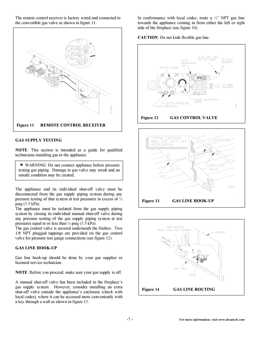
The remote control receiver is factory wired and connected to the convertible gas valve as shown in figure 11.
Figure 11 REMOTE CONTROL RECEIVER |
GAS SUPPLY TESTING
NOTE: This section is intended as a guide for qualified technicians installing gas to the appliance.
![]() WARNING: Do not connect appliance before pressure testing gas piping. Damage to gas valve may result and an unsafe condition may be created.
WARNING: Do not connect appliance before pressure testing gas piping. Damage to gas valve may result and an unsafe condition may be created.
The appliance and its individual
The appliance must be isolated from the gas supply piping system by closing its individual manual
The gas control valve is secured underneath the firebox. Two 1/8 NPT plugged tappings are provided on the gas control valve for pressure test gauge connections (see figure 12).
GAS LINE HOOK-UP
Gas line
NOTE: Before you proceed, make sure your gas supply is off.
A manual
In conformance with local codes, route a ½” NPT gas line towards the appliance coming in from either the left or right side of the fireplace (see figure 14).
CAUTION: Do not kink flexible gas line.
Figure 12 | GAS CONTROL VALVE |
Figure 13 | GAS LINE |
Figure 14 GAS LINE ROUTING
For more information, visit www.desatech.com |