SELECTING LOCATION

To determine the safest and most efficient location for your appli- ance, you must take into consideration the following guidelines:

1.The location must allow for proper clearances (see Clearances, next column).

2.Consider a location where heat output would not be affected by drafts, air conditioning ducts, windows or doors.

3.A location that avoids the cutting of joists or roof rafters will make installation easier. Figure 2 shows a plan view of a few common locations.

Flush installations are recommended where living space is

limited or at a premium and since the space required to enclose

the appliance would be located beyond an outside wall, this would

also reduce the cutting of joists, roof rafters and such. Check local

codes for any restrictions.


Projected installations can extend any distance into the room.

A projection may be ideal for a new addition on an existing, fin-

ished wall.


Corner installations make use of space that may not normally

be used and provides a wider and more efficient range for radiant

heat transference.


Internal wall installationsprovide a discreet option for room sepa-

ration and can also be ideal as an addition to an existing wall.


CORNER

INTERNAL WALL

INSTALLATION

INSTALLATION


FULL

FLUSH

INSTALLATION

PROJECTION


INSTALLATION


Figure 2 - Possible Locations for Installing Appliance

5

PRE-INSTALLATION

PREPARATION

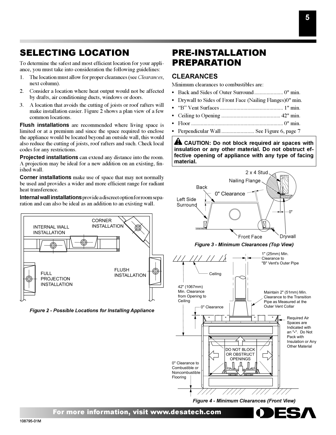
CLEARANCES

Minimum clearances to combustibles are:

• Back and Sides of Outer Surround ..................... 0" min.

• Drywall to Sides of Front Face (Nailing Flanges)0" min.

“B” Vent Surfaces

1" min.

Ceiling to Opening

42" min.

Floor

0" min.

Perpendicular Wall

See Figure 6, page 7

CAUTION: Do not block required air spaces with insulation or any other material. Do not obstruct ef- fective opening of appliance with any type of facing material.

2 x 4 Stud

Nailing Flange

Back

0" Clearance

Left Side

Surround

0"


Front Face


Drywall

Figure 3 - Minimum Clearances (Top View)


1" (25mm) Min.


Clearance to


"B" Vent's Outer Pipe

Ceiling


42" (1067mm)


Min. Clearance


Maintain 2" (51mm) Min.

from Opening to


Clearance to the Transition

Ceiling


Pipe as Measured at the

0" Clearance


Outer Vent Collar


*

*

*

*

Required Air


Spaces are


Indicated with


an "

". Do Not


*


Pack with


Insulation or Any


DO NOT BLOCK


Other Material


OR OBSTRUCT


0" Clearance to


OPENINGS


Combustible or


Noncombustible


Flooring


Figure 4 - Minimum Clearances (Front View)

For more information, visit www.desatech.com

108795-01M

Page 5
Image 5
Desa VM36P, H) AND VM42P(B, H) AND VM42(B installation manual Selecting Location, PRE-INSTALLATION Preparation, Clearances

VM36P, H) AND VM42(B, M42P, H) AND VM42P(B, M36P specifications

Desa H), M36P, H) and VM42P(B, M42P, H) and VM42(B are notable entities in the realm of technological solutions, particularly in the fields of engineering and manufacturing. These designations often pertain to advanced machine models or systems that incorporate various characteristics tailored for specific industrial applications.

The Desa H) series is recognized for its robust performance in industrial settings. It typically features enhanced efficiency and durability, making it suitable for rigorous operational environments. The key technologies integrated into the Desa H) models include high-performance motors and precision control systems that ensure optimal functionality. In particular, these systems are designed to minimize energy consumption while maximizing output across diverse applications.

Meanwhile, the M36P and its variants, including the M36P,H), are engineered with versatility in mind. They are equipped with modular components that allow for easy customization based on user requirements. This adaptability is a significant advantage, as it enables operators to modify the system to suit various tasks without extensive reconfiguration. Noteworthy features of the M36P series include advanced user interfaces that facilitate ease of operation and monitoring.

The VM42P(B, M42P, H) series takes innovation a step further by integrating state-of-the-art automation technologies. With features like smart sensors and AI-driven analytics, the VM42 models provide unprecedented levels of precision and reliability. These technologies enable predictive maintenance, allowing users to anticipate potential issues before they arise, thus reducing downtime and operational costs. The VM42(B) variant is particularly appreciated for its high throughput capabilities, making it ideal for mass production settings.

All models share common characteristics such as rugged construction, user-friendly interfaces, and compliance with international safety standards. Additionally, they are designed for scalability, which ensures that businesses can expand their operations with ease as demand grows. Enhanced connectivity options and IoT integration further allow for real-time data analysis and remote monitoring, fostering smarter production environments.

In summary, the Desa H), M36P, H) and VM42P(B, M42P, H) and VM42(B series represent a fusion of innovative engineering and practical application. Each model’s distinct features cater to a broad range of industrial needs, making them indispensable tools in modern manufacturing and engineering landscapes. Through their commitment to efficiency, adaptability, and intelligent technology, these systems pave the way for enhanced productivity and sustainability in various sectors.