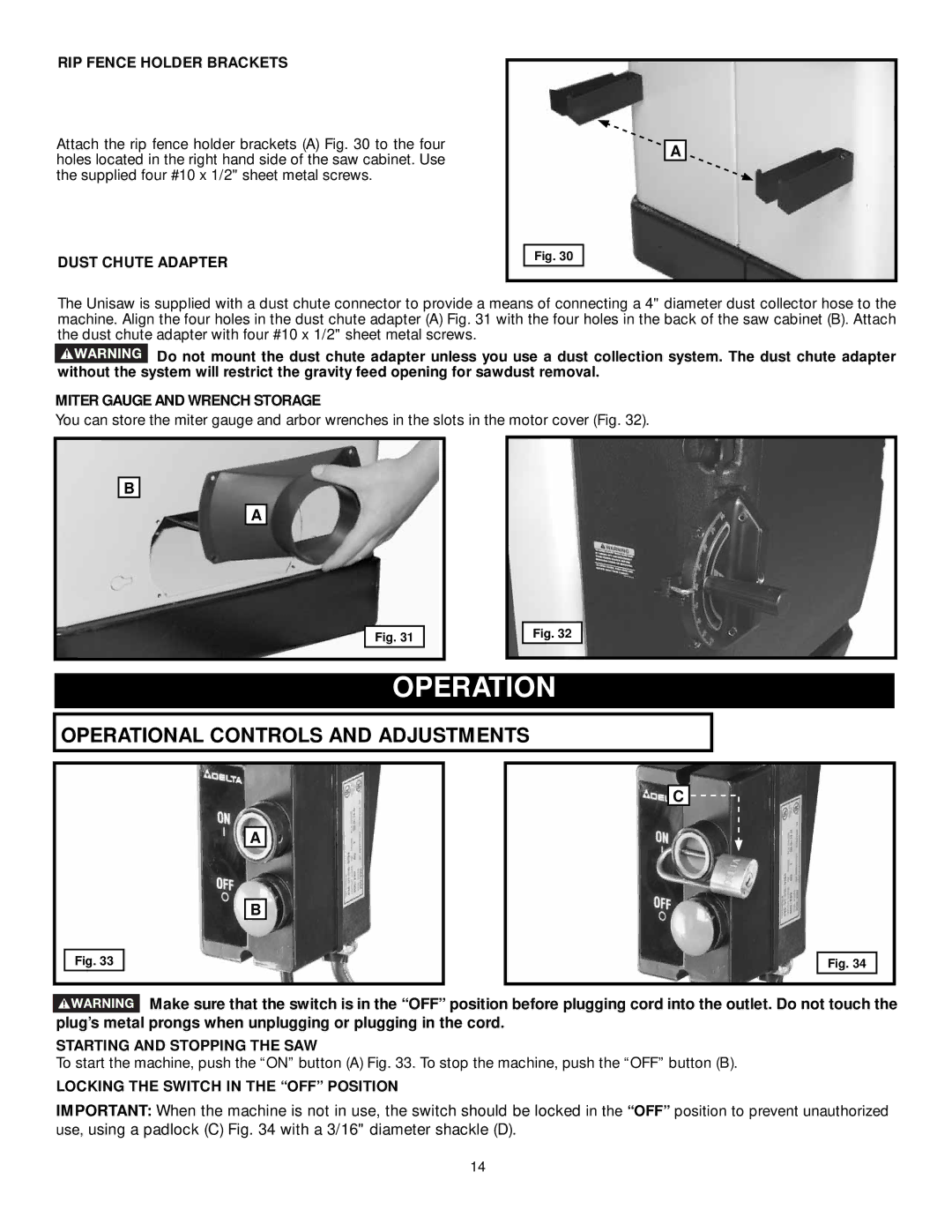
RIP FENCE HOLDER BRACKETS
Attach the rip fence holder brackets (A) Fig. 30 to the four holes located in the right hand side of the saw cabinet. Use the supplied four #10 x 1/2" sheet metal screws.
DUST CHUTE ADAPTER
Fig. 30
A
The Unisaw is supplied with a dust chute connector to provide a means of connecting a 4" diameter dust collector hose to the machine. Align the four holes in the dust chute adapter (A) Fig. 31 with the four holes in the back of the saw cabinet (B). Attach the dust chute adapter with four #10 x 1/2" sheet metal screws.
![]() Do not mount the dust chute adapter unless you use a dust collection system. The dust chute adapter without the system will restrict the gravity feed opening for sawdust removal.
Do not mount the dust chute adapter unless you use a dust collection system. The dust chute adapter without the system will restrict the gravity feed opening for sawdust removal.
MITER GAUGE AND WRENCH STORAGE
You can store the miter gauge and arbor wrenches in the slots in the motor cover (Fig. 32).
B
A
Fig. 31
Fig. 32
OPERATION
OPERATIONAL CONTROLS AND ADJUSTMENTS
A
B
Fig. 33
C ![]()
![]()
Fig. 34
![]() Make sure that the switch is in the “OFF” position before plugging cord into the outlet. Do not touch the plug’s metal prongs when unplugging or plugging in the cord.
Make sure that the switch is in the “OFF” position before plugging cord into the outlet. Do not touch the plug’s metal prongs when unplugging or plugging in the cord.
STARTING AND STOPPING THE SAW
To start the machine, push the “ON” button (A) Fig. 33. To stop the machine, push the “OFF” button (B).
LOCKING THE SWITCH IN THE “OFF” POSITION
IMPORTANT: When the machine is not in use, the switch should be locked in the “OFF” position to prevent unauthorized use, using a padlock (C) Fig. 34 with a 3/16" diameter shackle (D).
14