OPERATING CONTROLS AND ADJUSTMENTS
START-STOP SWITCH
The
A
B
Fig. 18
FENCE OPERATION
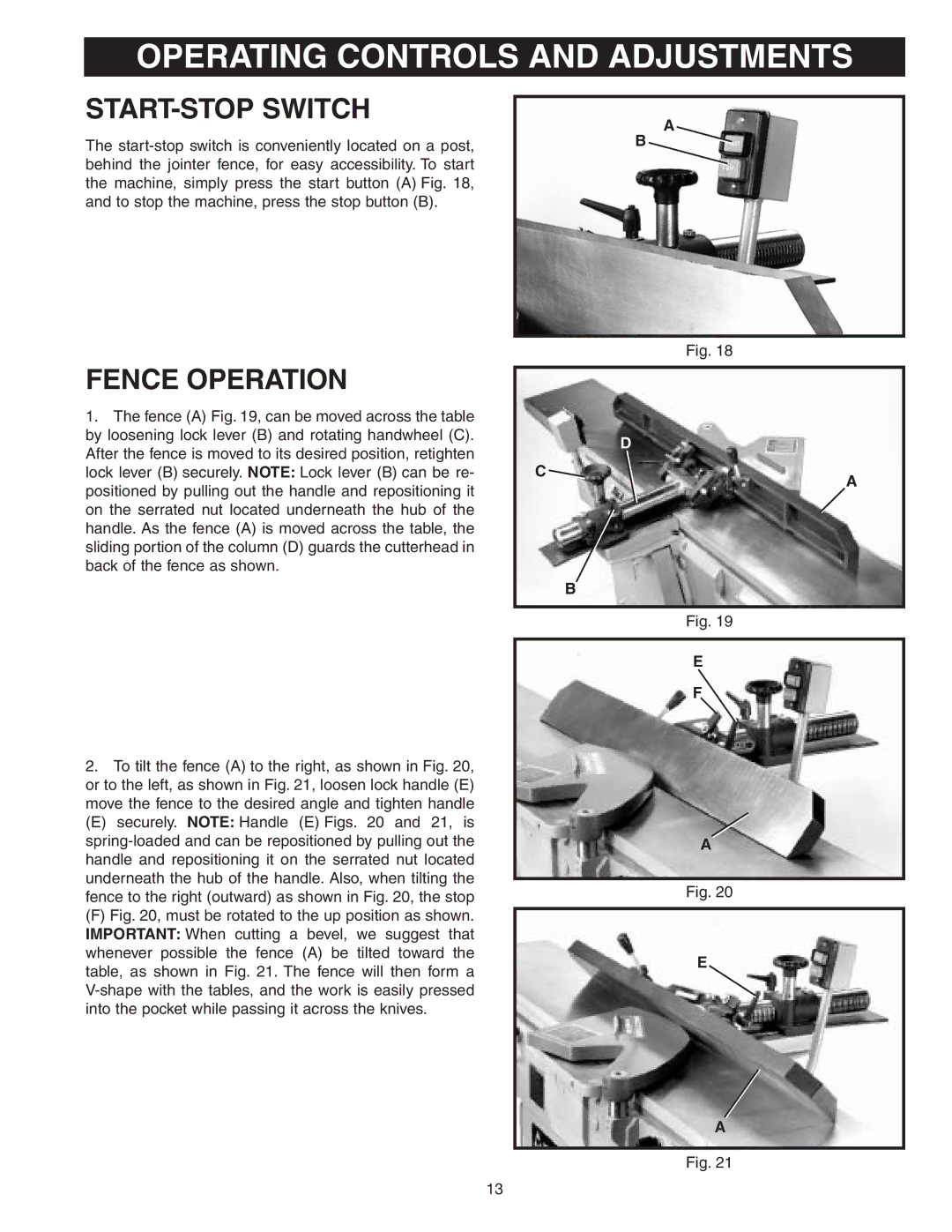
1.The fence (A) Fig. 19, can be moved across the table by loosening lock lever (B) and rotating handwheel (C). After the fence is moved to its desired position, retighten lock lever (B) securely. NOTE: Lock lever (B) can be re- positioned by pulling out the handle and repositioning it on the serrated nut located underneath the hub of the handle. As the fence (A) is moved across the table, the sliding portion of the column (D) guards the cutterhead in back of the fence as shown.
2.To tilt the fence (A) to the right, as shown in Fig. 20, or to the left, as shown in Fig. 21, loosen lock handle (E) move the fence to the desired angle and tighten handle
(E) securely. NOTE: Handle (E) Figs. 20 and 21, is
(F) Fig. 20, must be rotated to the up position as shown. IMPORTANT: When cutting a bevel, we suggest that whenever possible the fence (A) be tilted toward the table, as shown in Fig. 21. The fence will then form a V-shape with the tables, and the work is easily pressed into the pocket while passing it across the knives.
D
C
A
B
Fig. 19
E
F
A
Fig. 20
E
A
Fig. 21
13