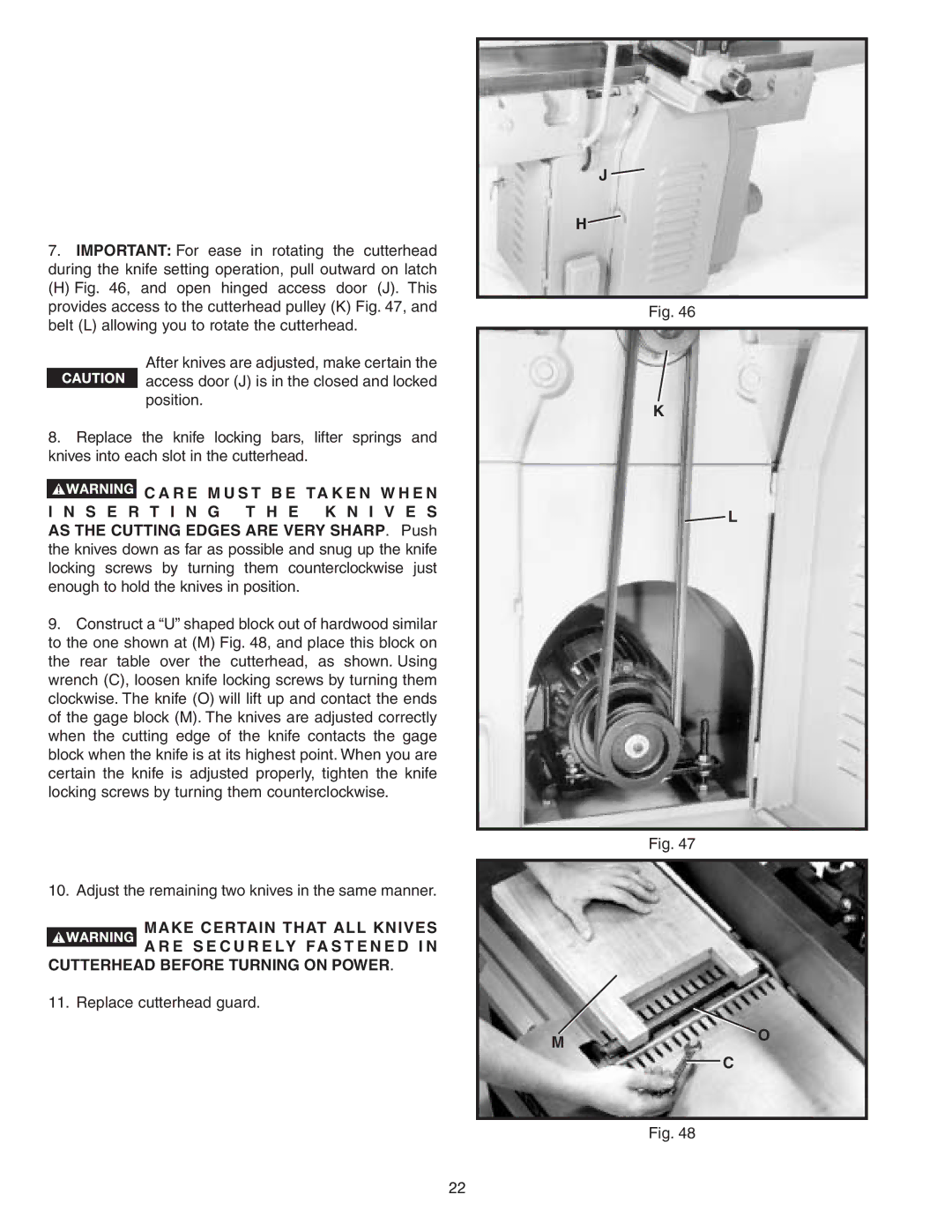
7.IMPORTANT: For ease in rotating the cutterhead during the knife setting operation, pull outward on latch
(H) Fig. 46, and open hinged access door (J). This provides access to the cutterhead pulley (K) Fig. 47, and belt (L) allowing you to rotate the cutterhead.
After knives are adjusted, make certain the  access door (J) is in the closed and locked
position.
8.Replace the knife locking bars, lifter springs and knives into each slot in the cutterhead.
![]() C A R E M U S T B E TA K E N W H E N I N S E R T I N G T H E K N I V E S AS THE CUTTING EDGES ARE VERY SHARP. Push the knives down as far as possible and snug up the knife locking screws by turning them counterclockwise just enough to hold the knives in position.
C A R E M U S T B E TA K E N W H E N I N S E R T I N G T H E K N I V E S AS THE CUTTING EDGES ARE VERY SHARP. Push the knives down as far as possible and snug up the knife locking screws by turning them counterclockwise just enough to hold the knives in position.
9.Construct a “U” shaped block out of hardwood similar to the one shown at (M) Fig. 48, and place this block on the rear table over the cutterhead, as shown. Using wrench (C), loosen knife locking screws by turning them clockwise. The knife (O) will lift up and contact the ends of the gage block (M). The knives are adjusted correctly when the cutting edge of the knife contacts the gage block when the knife is at its highest point. When you are certain the knife is adjusted properly, tighten the knife locking screws by turning them counterclockwise.
10.Adjust the remaining two knives in the same manner.
MAKE CERTAIN THAT ALL KNIVES A R E S E C U R E LY FA S T E N E D I N
CUTTERHEAD BEFORE TURNING ON POWER.
11. Replace cutterhead guard.
J![]()
H![]()
Fig. 46
K
![]() L
L
Fig. 47
MO  C
C
Fig. 48
22
