C![]()
Fig. 19
ADJUSTING THE TOOL REST
D![]()
![]()
C ![]()
![]() G
G ![]()
![]()
Fig. 20
Disconnect the machine from the power source!
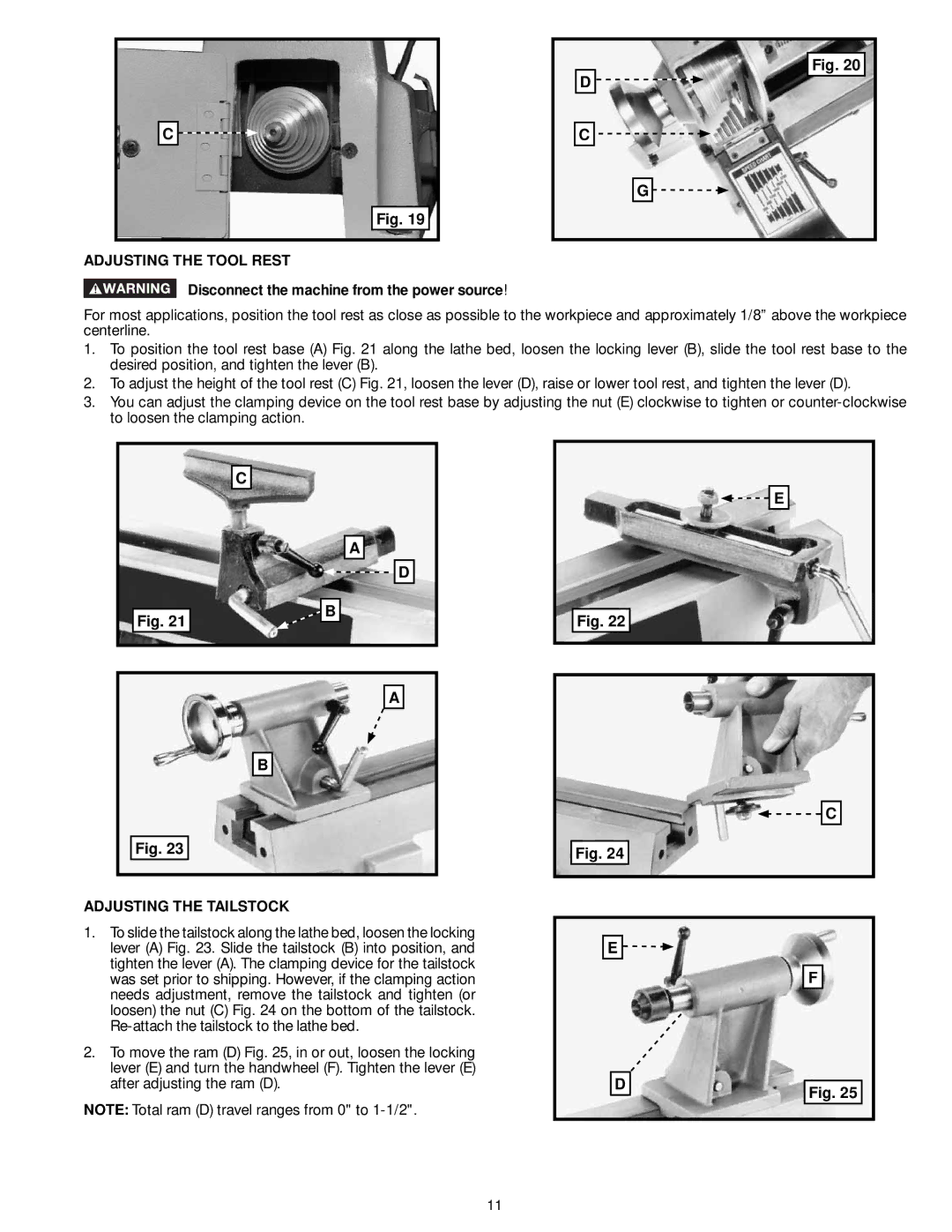
For most applications, position the tool rest as close as possible to the workpiece and approximately 1/8” above the workpiece centerline.
1.To position the tool rest base (A) Fig. 21 along the lathe bed, loosen the locking lever (B), slide the tool rest base to the desired position, and tighten the lever (B).
2.To adjust the height of the tool rest (C) Fig. 21, loosen the lever (D), raise or lower tool rest, and tighten the lever (D).
3.You can adjust the clamping device on the tool rest base by adjusting the nut (E) clockwise to tighten or
C
![]()
![]() E
E
Fig. 21
A
D
B
A
Fig. 22
B
Fig. 23
ADJUSTING THE TAILSTOCK
1.To slide the tailstock along the lathe bed, loosen the locking lever (A) Fig. 23. Slide the tailstock (B) into position, and tighten the lever (A). The clamping device for the tailstock was set prior to shipping. However, if the clamping action needs adjustment, remove the tailstock and tighten (or loosen) the nut (C) Fig. 24 on the bottom of the tailstock.
2.To move the ram (D) Fig. 25, in or out, loosen the locking lever (E) and turn the handwheel (F). Tighten the lever (E) after adjusting the ram (D).
NOTE: Total ram (D) travel ranges from 0" to
![]()
![]() C
C
Fig. 24
E ![]()
![]()
F
D
Fig. 25
11
